Do you have a question about the Toshiba RAS-10N3KVR-E and is the answer not in the manual?
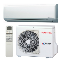
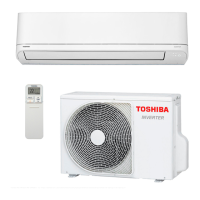
Specific technical data for the RAS-10N3KVR-E indoor and RAS-10N3AVR-E outdoor units.
Graphs illustrating current vs. compressor speed for cooling and heating modes.
Charts showing how cooling and heating capacity varies with outdoor temperature.
Detailed technical specifications for the RAS-13N3KVR-E indoor and RAS-13N3AVR-E outdoor units.
Critical safety procedures for handling R410A refrigerant during installation and servicing.
Guidelines and methods for installing refrigerant piping, including materials and joints.
List of specialized tools required for handling R410A refrigerant and piping.
Step-by-step instructions for recharging refrigerant into the air conditioner system.
Techniques and materials for brazing refrigerant pipes, including flux types and usage.
Detailed views and dimensions of the indoor unit and its mounting hardware.
Detailed views and dimensions of the outdoor unit, including mounting and connections.
Specifications for electrical parts within the indoor unit, such as fan motor and sensors.
Specifications for electrical parts within the outdoor unit, including compressor and motors.
Schematic representation of the refrigerant flow through the indoor and outdoor units.
Table of operational data including temperatures, pressures, and fan speeds under various conditions.
Schematic of the indoor unit's control system, including sensors and MCU functions.
Schematic of the outdoor unit's control system, focusing on the inverter assembly and its functions.
Description of the indoor and outdoor unit controllers and their roles in system operation.
Explanation of basic operation, cooling/heating, AUTO, DRY, and fan motor controls.
Instructions for setting, cancelling, and the behavior of the auto restart function.
Details on remote controller buttons, operation modes, and display indicators.
Visual guide for the physical placement and mounting of the indoor and outdoor units.
Information on optional installation parts, fixing arrangements, and preliminary checks.
Specific steps for installing the indoor unit, including placement, hole cutting, wiring, and drainage.
Specific steps for installing the outdoor unit, including placement, refrigerant piping, and electrical work.
Includes gas leak tests, remote control settings, test operations, and auto restart setup.
Basic checks to confirm power supply, voltage, and fuse status before deeper diagnosis.
Methods for initial fault diagnosis, including LED indicators and symptom analysis.
Interpreting flashing LED patterns on the indoor unit to identify specific error codes.
Using the remote controller in service mode to retrieve and interpret diagnostic check codes.
Detailed troubleshooting steps for various symptoms, including wiring, sensors, motors, and PC boards.
Procedures for removing and replacing parts within the indoor unit, such as the front panel and microcomputer.
Steps for accessing and replacing the microcomputer assembly in the indoor unit.
Procedures for removing and replacing parts within the outdoor unit, including cabinets and motors.
Illustrated breakdown of indoor unit components with corresponding part numbers.
Exploded view and parts list specifically for the E-Parts assembly of the indoor unit.
Illustrated breakdown of outdoor unit components with corresponding part numbers.
Diagram showing the P.C. board layout and sensor resistance values versus temperature.
| Cooling Capacity | 2.5 kW |
|---|---|
| Heating Capacity | 3.2 kW |
| Refrigerant | R410A |
| Power Supply | 220-240V, 50Hz |
| Energy Efficiency Ratio (EER) | 3.21 |
| Coefficient of Performance (COP) | 3.61 |
| Outdoor Unit Dimensions (W x H x D) | 660 x 530 x 240 mm |
| Indoor Unit Weight | 9 kg |
| Type | Split System Air Conditioner |
| Noise Level (Outdoor) | 50 dB(A) |