Do you have a question about the Toshiba RAS-10NKV-E and is the answer not in the manual?
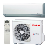
Detailed technical specifications of the indoor and outdoor units, including capacity, power, and dimensions.
Graphs illustrating current vs. compressor speed and capacity variation with temperature.
Graphs showing how cooling and heating capacity changes with outdoor temperature.
Crucial safety precautions for installation and servicing with R410A refrigerant.
Guidelines for installing refrigerant piping, including materials, joints, and processing.
Lists of R410A-specific tools and general tools required for installation.
Step-by-step procedure for safely recharging the air conditioner with refrigerant.
Information on brazing materials, flux, and methods to prevent oxidation.
Diagrams showing the dimensions and physical features of the indoor unit.
Diagrams illustrating the dimensions and physical features of the outdoor unit.
Wiring diagram for the indoor unit with checks for failure diagnosis.
Wiring diagram for the outdoor unit, detailing its electrical connections.
List of electrical components for the indoor unit with their specifications.
List of electrical components for the outdoor unit with their ratings.
Schematic illustrating the flow of refrigerant through the system components.
Table containing operational data for cooling and heating modes.
Diagram showing the control functions and signals of the indoor unit.
Block diagram detailing the control logic of the outdoor unit's inverter assembly.
Overview of control logic, basic functions, and modes like capacity, fan, and louvers.
Detailed descriptions of Cooling, DRY, Heating, and Automatic operation modes.
How to use temporary operations, auto restart, and manage the filter check lamp.
Explains remote control buttons, functions, and display indications.
Safety cautions, installation diagrams, parts, and tools for installation.
Specific steps for indoor unit installation, including placement, wiring, and drainage.
Specific steps for outdoor unit installation, including piping, wiring, testing, and setup.
First confirmation steps, identifying normal operations, and primary judgment methods.
Interpreting indoor unit LED codes and using remote control for self-diagnosis.
Diagnosing issues based on symptoms, wiring failures, and error codes.
Diagnosing outdoor unit inverter issues and checking main parts like PC boards and fan motors.
Methods for checking PC boards, motors, and other key components.
Simple procedure to judge the condition of the outdoor fan motor.
Procedures for replacing indoor unit parts like front panel, electrical parts, and louvers.
Steps for replacing the microcomputer and associated components.
Procedures for replacing outdoor unit parts like cabinets, inverter, and compressor.
Exploded view and parts list for the indoor unit's E-Parts assembly.
Exploded view and parts list for the main indoor unit components.
Exploded view and parts list for the main outdoor unit components.
Exploded view and parts list for the outdoor unit's E-Parts assembly.
| Type | Split System |
|---|---|
| Cooling Capacity | 2.5 kW |
| Heating Capacity | 3.2 kW |
| Refrigerant | R410A |
| Power Supply | 220-240V, 50Hz |
| Energy Efficiency Ratio (EER) | 3.21 |
| Coefficient of Performance (COP) | 3.61 |
| Indoor Unit Weight | 9 kg |
| Noise Level (Outdoor Unit) | 50 dB(A) |