Do you have a question about the Toshiba RAS-10NKH and is the answer not in the manual?
Diagrams and dimensions of the indoor unit.
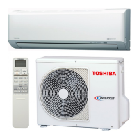
Exploded view and dimensions of the outdoor unit.
Procedures and precautions for indoor unit installation.
Detailed instructions and precautions for pipe flaring.
Guidelines for pipe bending and connection.
Electrical parts for the indoor unit with specifications.
Electrical parts for the outdoor unit with specifications.
Explains display panel indicators and control panel operations.
Details the functions of various buttons on the remote control.
Explains the display indicators on the remote controller.
Guidance on remote controller placement, mounting, and battery replacement.
How the unit automatically selects cooling, heating, or fan modes.
Manual selection of heating, cooling, or fan only modes.
Instructions for operating the unit in dry mode for humidity control.
How to set, reserve, and cancel ON/OFF timers.
How to adjust the vertical louver for desired air flow direction.
Adjusting horizontal grilles and automatic swing functions.
Description of fan-only mode operation and air volume.
Description of cooling mode operation, fan control.
Description of heating mode operation, fan control, and louver movement.
Explanation of the economy mode for quiet and mild operation.
Details on dry mode for humidity control and compressor cycling.
How the unit selects modes based on room temperature.
Mechanisms for current, high temperature, and antifreezing control.
Conditions and control for defrost operation and indicator lamp.
Initial checks, power, wiring, and misleading good operations.
Primary judgement of trouble sources and indoor unit controller roles.
Interpreting block displays for self-diagnosis and judging abnormal spots.
Procedures for self-diagnosis using the remote controller and service modes.
Using check codes and key operations for self-diagnosis.
Flowchart for troubleshooting when the unit does not operate at all.
Flowcharts for power relay not operating or indoor fan not operating.
Flowcharts for compressor not operating and sensor issues.
Steps to check the remote control and its interaction with the indoor unit.
Steps to check the PC board for defects, voltage, and fuses.
Checking sensor resistance values and reducing anti-restart timer.
Exploded view and parts list for the indoor unit.
Exploded view and parts list for the outdoor unit.
Detailed list of PC board components and their part numbers.
| Type | Split System |
|---|---|
| Cooling Capacity | 2.8 kW |
| Heating Capacity | 3.2 kW |
| Power Supply | 220-240V, 50Hz |
| Refrigerant | R410A |
| Energy Efficiency Ratio (EER) | 3.21 |
| Coefficient of Performance (COP) | 3.61 |
| Indoor Unit Weight | 9 kg |
| Noise Level (Outdoor) | 50 dB(A) |