Do you have a question about the Toshiba RAS-13SKVR-E and is the answer not in the manual?
| Cooling Capacity | 3.5 kW |
|---|---|
| Heating Capacity | 4.0 kW |
| Refrigerant | R32 |
| Power Supply | 220-240V, 50Hz |
| Energy Efficiency Ratio (EER) | 3.21 |
| Indoor Unit Dimensions (WxHxD) | 798 x 293 x 230 mm |
| Outdoor Unit Dimensions (WxHxD) | 780 x 550 x 290 mm |
| Indoor Unit Weight | 9 kg |
| Outdoor Unit Noise Level | 50 dB(A) |
Ensures safe use of power cord and general servicing practices.
Precautions for safe handling of R410A refrigerant during installation and servicing.
Details electrical safety, high voltage precautions, and proper wiring/grounding.
Important warnings regarding installation location, unit modification, electrical safety, and refrigerant handling.
Cautions related to installation environment, physical hazards, and seismic protection.
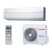
Presents detailed technical specifications for different air conditioner models.
Graphical representation of cooling/heating performance based on compressor speed.
Illustrates how cooling and heating capacity vary with outdoor temperature.
Safety guidelines for installation and servicing of R410A refrigerant systems.
Specifies required piping materials and joint types suitable for R410A refrigerant.
Details procedures and precautions for cutting and preparing refrigerant piping materials.
Specifies precise dimensions for R410A and R22 flare processing.
Instructions for connecting refrigerant flares and required tightening torque.
Lists essential tools for R410A installation and general tools.
Step-by-step guide for safely recharging refrigerant into the system.
Information on brazing filler materials and the function/types of flux.
Details flux characteristics, types, brazing methods, and oxidation prevention.
Diagrams and dimensions illustrating the construction of the indoor unit.
Diagrams and dimensions for the outdoor unit, including installation clearances.
Electrical wiring schematic for RAS-13SKV/SAV and related models.
Electrical wiring schematic for RAS-16SKV/SAV and related models.
Specifications for electrical components in the indoor unit.
Specifications for electrical components in the outdoor unit.
Diagram showing the refrigerant cycle path for various model series.
Performance data for cooling and heating modes under specified conditions.
Block diagram illustrating indoor unit control logic and functions.
Block diagram detailing the outdoor unit's inverter assembly and control system.
Overview of the air conditioner's control system, unit roles, and communication.
Explanation of basic operation modes: Cooling, Heating, AUTO, and DRY.
Details on controlling indoor/outdoor fan speed and louver direction.
Description of advanced features like defrost, ECO, air purifying, and self-cleaning.
Detailed explanation of indoor fan motor speed control in various modes.
Procedure for controlling outdoor fan motor speed based on conditions.
Methods for controlling unit capacity and managing current for performance.
Protective controls based on indoor heat exchanger temperature.
Process for defrosting the outdoor heat exchanger during heating.
Functions and adjustments for controlling the louvre's position and airflow.
Explanation of the ECO mode for energy saving operations.
Procedures for temporary operation and using the air purifying function.
Handling air purifier abnormalities and discharge temperature control.
Operation of the Pulse Modulating Valve for refrigerant flow regulation.
Details on the self-cleaning function to maintain indoor unit cleanliness.
Instructions for canceling and setting the self-cleaning operation.
Procedure for selecting remote control mode A or B for multi-unit systems.
Explanation of QUIET and COMFORT SLEEP modes for user comfort.
Functions for One-Touch, Hi-POWER, and filter indicator status.
Steps to enable the auto restart function for power failure recovery.
Procedure to cancel auto restart and handle timer issues during power failure.
Overview of remote control buttons and display indicators.
Instructions for operating various functions using the remote control.
Details on advanced remote operations like Preset, Quiet, and Sleep Timer.
Explanation of indicators displayed on the remote control.
Safety precautions and warnings before commencing installation.
Lists optional parts, accessories, and included items for installation.
Lists tools required for R410A installation, noting R22 differences.
Guidelines for indoor unit placement and remote controller positioning.
Requirements and procedures for electrical work and wiring connections.
Steps for installing piping and the drain hose, including panel modification.
Details on attaching drain components and connecting pipes for various configurations.
Instructions for mounting the indoor unit and ensuring proper drainage.
Key considerations for selecting the optimal outdoor unit installation location.
Procedures for outdoor unit drainage and refrigerant piping connection.
Step-by-step guide for performing evacuation and air purging.
Instructions for connecting power and control wiring to the outdoor unit.
Procedures for gas leak testing and initial system operation verification.
Configuration of auto restart and remote control A/B selection.
Overview of troubleshooting steps for diagnosing unit problems.
Critical safety warnings for handling the 3DV inverter module.
Safety measures for inspecting/replacing circuit boards, especially high voltage components.
Checks for power supply, voltage, and normal operation behaviors.
Interpretation of indoor unit LED flashing patterns for error diagnosis.
Procedure to enter service mode and read diagnostic check codes.
Troubleshooting actions based on identified check codes and causes.
Troubleshooting steps for indoor unit power-on issues.
Flowchart for diagnosing indoor fan motor non-operation.
Troubleshooting steps for indoor fan motor auto-start issues.
Procedure for checking AC fan motor winding resistance.
Flowchart for diagnosing and resolving remote controller problems.
Troubleshooting wiring failures affecting outdoor unit operation.
Troubleshooting for miswiring (1C) and sensor errors (1E).
Procedure to check the functionality of the air purifier system.
Steps to verify the functionality of the minus ion generator.
Summarized diagnostic process for the outdoor unit inverter assembly.
Precautions and procedures for checking the indoor unit P.C. board.
Check procedures for indoor unit components like power supply and motors.
P.C. board layout and sensor characteristics for RAS-10/13 Series.
P.C. board layout and sensor characteristics for RAS-16 Series.
Procedures for checking indoor unit sensors, remote control, and fan motors.
Procedures for checking outdoor unit components: compressor, motors, sensors, valves.
Methods for checking electrolytic capacitors and diode blocks.
Procedure to diagnose outdoor fan motor condition based on symptoms and causes.
Steps for safely removing and replacing the indoor unit front panel.
Procedure for replacing the indoor unit's high voltage generator.
Steps for removing and replacing the indoor unit's electric parts box.
Procedure for removing and replacing the horizontal louver.
Steps for removing and replacing the indoor unit heat exchanger (evaporator).
Procedure for removing and replacing the fan motor bearing.
Steps for removing and replacing the indoor unit fan motor.
Instructions for correctly reassembling the cross flow fan after motor replacement.
Microcomputer replacement and P.C. board layout for RAS-10/13 Series.
P.C. board layout for the RAS-16 Series.
Procedures for removing and attaching outdoor unit cabinets and covers.
Steps for detaching and attaching the front cabinet of the outdoor unit.
Procedure for checking, discharging, and replacing the outdoor unit's inverter assembly.
Procedure for replacing the outdoor unit control board assembly.
Procedures for removing/installing outdoor unit side cabinets and fan motor.
Procedures for removing and replacing the outdoor unit compressor and reactor.
Procedures for replacing outdoor unit expansion valve coil and fan guard.
Instructions for installing and checking outdoor unit sensors (TE, TS, TD, TO).
Method for replacing temperature sensors, including parts list.
Exploded view and parts list for indoor unit components.
Continued exploded view and parts list for indoor unit components.
Exploded view and parts list for outdoor unit components.
Continued parts list for outdoor unit components.
Layout diagrams of the unit's P.C. boards.