Do you have a question about the Toshiba RAS-13SKX and is the answer not in the manual?
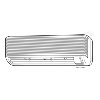
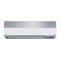
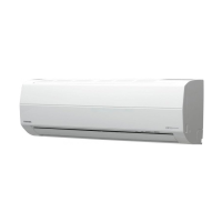
Detailed illustration of the indoor unit's construction and components.
Detailed illustration of the outdoor unit's construction and components.
Lists electrical parts and their specifications for the indoor unit.
Lists electrical parts and their specifications for the outdoor unit.
Describes the operation when the remote control mode is set to FAN ONLY.
Explains how compressor, outdoor fan, and operation display are controlled during COOL mode.
Details how to set the louver position using the remote control.
Describes compressor, outdoor fan, and operation display control in DRY mode.
Explains selection of Cooling or Dry mode based on room temperature in AUTO mode.
Describes the quiet operation with controlled airflow when ECONO. mode is selected.
Explains prevention of indoor heat exchanger freezing by monitoring its temperature.
Unit restarts and resumes set conditions after power supply interruption.
Procedures for setting and canceling the Auto Restart function using the TEMPORARY button.
Explains cancellation of timer operations due to power failure.
Important safety warnings and precautions for installation personnel and users.
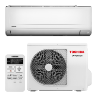
Illustrates the physical placement and mounting of indoor and outdoor units.
Lists standard and optional parts required for installation.
Covers selecting location, cutting holes, and mounting the indoor unit.
Details electrical requirements, wiring, and power source connection for the indoor unit.
Instructions on connecting the main power cord and internal wiring to the indoor unit.
Guides on connecting refrigerant pipes and installing the drain hose for the indoor unit.
Steps for physically mounting the indoor unit onto the installation plate.
Covers selecting location and mounting the outdoor unit.
Detailed steps for connecting the refrigerant pipes to the outdoor unit.
Instructions for connecting the electrical wiring to the outdoor unit's terminal block.
Covers gas leak test, test operation, and auto restart setting.
Initial checks to perform before diagnosing issues.
Explains normal operations that might appear as issues if misunderstood.
Methods for initial diagnosis and identifying the source of problems.
Describes the functions of the indoor unit's control system.
How the unit displays self-diagnosis results and identifies faults.
Procedures for performing self-diagnosis using the remote control and interpreting results.
Flowchart to diagnose why the unit does not turn on at all.
Troubleshooting steps if the unit fails to power on after a PC board replacement.
Flowchart for diagnosing issues when the outdoor unit is not operating.
Troubleshooting steps when only the compressor fails to operate.
Troubleshooting steps when only the outdoor fan fails to operate.
Troubleshooting steps when only the indoor fan fails to operate.
Procedures for checking remote control and indoor PC board functionality.
Procedures for inspecting the indoor unit's printed circuit board for faults.
Step-by-step guide for checking various components and their readings.
Diagrams showing the top and bottom layouts of the indoor unit's PC board.
Instructions for modifying the anti-restart timer's operation duration.
Procedures for replacing parts of the indoor unit.
Steps for replacing the microcomputer and related components.
Procedures for replacing parts of the outdoor unit.
Exploded view and parts list for the indoor unit.
Continuation of exploded view and parts list for the indoor unit.
Exploded view and parts list for the outdoor unit.
| Brand | Toshiba |
|---|---|
| Model | RAS-13SKX |
| Category | Air Conditioner |
| Language | English |