EasyManua.ls Logo

Toshiba RAS-13UKPX4 User Manual

Toshiba RAS-13UKPX4
93 pages
To Next Page IconTo Next Page
Page #1 background imageLoading...
Page #1 background image
FILE NO. SVM-05001-3
SERVICE MANUAL
AIR CONDITIONER
SPLIT WALL TYPE
RAS-13UKHP-E4 / RAS-13UAH-E4
RAS-10UKHP-E4 / RAS-10UAH-E4
RAS-13UKP-E4 / RAS-13UA-E4
RAS-10UKP-E4 / RAS-10UA-E4
RAS-13UKPX4 / RAS-13UAX4
RAS-10UKPX4 / RAS-10UAX4
RAS-12UKPX4 / RAS-12UAX4
RAS-07UKHP-E4 / RAS-07UAH-E4
RAS-07UKP-E4 / RAS-07UA-E4
RAS-07UKPX4 / RAS-07UAX4
Revised on Nov, 2005

Table of Contents

Question and Answer IconNeed help?

Do you have a question about the Toshiba RAS-13UKPX4 and is the answer not in the manual?

Toshiba RAS-13UKPX4 Specifications

General IconGeneral
Cooling Capacity3.5 kW
Heating Capacity4.0 kW
RefrigerantR32
Weight (Indoor Unit)9 kg
Power Supply220-240V, 50Hz
Noise Level (Outdoor)49 dB

Summary

Specifications

Construction Views

Indoor Unit Construction

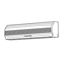
Visual representation and dimensions of the indoor unit.

Outdoor Unit Construction

Visual representation and dimensions of outdoor units.

Wiring Diagram

Wiring Diagram RAS-13UKHP-E4 / RAS-13UAH-E4

Electrical schematic for specific model series.

Wiring Diagram RAS-10UKHP-E4 / RAS-10UAH-E4

Electrical schematic for specific model series.

Wiring Diagram RAS-07UKHP-E4 / RAS-07UAH-E4

Electrical schematic for specific model series.

Wiring Diagram RAS-13UKP-E4 / RAS-13UA-E4

Electrical schematic for specific model series.

Wiring Diagram RAS-10UKP-E4 / RAS-10UA-E4, RAS-07UKP-E4 / RAS-07UA-E4

Electrical schematic for specific model series.

Wiring Diagram RAS-13UKPX4 / RAS-13UAX4, RAS-12UKPX4 / RAS-12UAX4

Electrical schematic for specific model series.

Wiring Diagram RAS-10UKPX4 / RAS-10UAX4, RAS-07UKPX4 / RAS-07UAX4

Electrical schematic for specific model series.

Specification of Electrical Parts

Indoor Unit Electrical Parts

Specs for electrical components in indoor units.

Outdoor Unit Electrical Parts

Specs for electrical components in outdoor units.

Outdoor Unit Electrical Parts

Specs for other outdoor units.

Outdoor Unit Electrical Parts

Specs for more outdoor units.

Outdoor Unit Electrical Parts

Specs for final outdoor units.

Refrigeration Cycle Diagram

RAS-13UKHP-E4 / RAS-13UAH-E4 Cycle Diagram

Illustrates refrigerant flow for specific models.

RAS-10UKHP-E4 / RAS-10UAH-E4 Cycle Diagram

Illustrates refrigerant flow for specific models.

RAS-07UKHP-E4 / RAS-07UAH-E4 Cycle Diagram

Illustrates refrigerant flow for specific models.

RAS-13UKP/UA/UKPX4/UAX4/UKPX4/UAX4 Cycle Diagram

Illustrates refrigerant flow for specific models.

RAS-10UKP/UA/UKPX4/UAX4 Cycle Diagram

Illustrates refrigerant flow for specific models.

RAS-07UKP/UA/UKPX4/UAX4 Cycle Diagram

Illustrates refrigerant flow for specific models.

Control Block Diagram

Control Block Diagram for UKHP/UAH Models

Diagram of control logic for specific indoor/outdoor units.

Control Block Diagram for UKP/UA/UKPX4/UAX4 Models

Diagram of control logic for various indoor/outdoor units.

Operation Description

Control Overview and Circuits

General control functions, sensors, and operation circuit details.

Standard Operation Modes

Cooling, Dry, Fan Only, and Heating modes.

Special Operation Modes

Automatic, Hi POWER, Temperature Limits, Low Temp.

Maintenance Features

Defrost, Current Limit, Auto Restart, Filter Check.

Advanced Modes

Self-Cleaning, Quiet, and Comfort Sleep modes.

Installation Procedure

Safety Cautions

Critical safety precautions before and during installation.

Installation Diagrams

Visual guides for installing indoor and outdoor units.

Unit Installation Procedures

Steps for installing indoor/outdoor units, piping, wiring.

Remote Control and Other Settings

Remote control setup and gas leak testing.

Troubleshooting

Basic Checks and Initial Judgement

Initial checks and primary fault diagnosis.

Remote Control Self-Diagnosis

Using remote control for fault codes and service modes.

Operational Flowcharts

Step-by-step guides for common unit failures.

Component Troubleshooting

Diagnosing issues with remote control and PC boards.

Part Replacement

Indoor Unit Part Replacement

Procedures for replacing parts of the indoor unit.

Outdoor Unit Part Replacement

Procedures for replacing parts of the outdoor unit.

Exploded Views and Parts List

Indoor Unit Exploded Views

Illustrated breakdown of indoor unit components.

Outdoor Unit Exploded Views

Illustrated breakdown of outdoor unit components.

Related product manuals