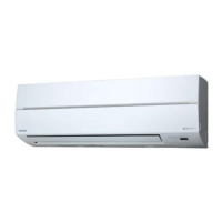
Do you have a question about the Toshiba RAS-16SAV2-E and is the answer not in the manual?
Essential precautions for installation, operation, and servicing.
Critical warnings regarding electrical hazards and high voltage circuits.
Detailed technical specifications for indoor and outdoor units.
Performance data curves related to compressor speed and temperature.
Critical safety measures for handling R410A refrigerant during installation.
Guidelines on selecting and using copper pipes and appropriate joints for R410A.
Lists specialized tools and their interchangeability for R410A systems.
Details different types of brazing fillers and their properties.
Explains the necessity and types of flux used in brazing.
Exploded views and dimensions of the indoor unit components.
Exploded views and dimensions of the outdoor unit components.
Electrical schematic for specific indoor/outdoor unit models.
Electrical schematic for the RAS-16SKV2-E model.
List of electrical components for the indoor unit with specifications.
List of electrical components for the outdoor unit with specifications.
Schematic showing the refrigerant flow for specific models.
Schematic showing the refrigerant flow for specific models.
Schematic showing the refrigerant flow for specific models.
Diagram illustrating the indoor unit's control logic and components.
Diagram showing the outdoor unit's control logic and inverter assembly.
Overview of the air conditioner's control system and its main functions.
Details the functions and responsibilities of the indoor unit controller.
Outlines the functions and responsibilities of the outdoor unit controller.
Covers basic operation, cooling/heating, AUTO, and DRY modes.
Details indoor and outdoor fan motor control and capacity adjustment.
Explains ECO, PRESET, QUIET, COMFORT SLEEP, and other special modes.
Step-by-step guide to enable or disable the auto restart feature.
Procedures for cancelling auto restart and handling power failures during timer operation.
Identifies buttons and indicators on the remote control unit.
Explains how to use various remote control functions like ONE-TOUCH, AUTO, DRY.
Visual guide showing the placement and connection of indoor and outdoor units.
Lists additional parts required for installation, such as piping.
Guidelines for selecting an appropriate location for the indoor unit.
Instructions for drilling holes and mounting the indoor unit's installation plate.
Procedures for electrical connections, wiring, and power supply requirements.
Steps for routing pipes, drain hoses, and ensuring proper insulation.
Guidelines for selecting a suitable location for the outdoor unit.
Instructions for water drainage and refrigerant piping connection procedures.
Steps for connecting power and communication cables to the outdoor unit.
Procedure for checking refrigerant gas leaks after installation.
Steps to perform test operation, set auto restart, and select remote control.
General steps and precautions for diagnosing and troubleshooting issues.
Initial checks, power confirmation, and interpreting indoor unit LED codes.
Guide on using the remote controller for detailed self-diagnosis and check codes.
Step-by-step diagnosis based on specific symptoms and component checks.
Step-by-step instructions for replacing major indoor unit components.
Procedures for disassembling and assembling the outdoor unit.
Visual parts breakdown and list for the indoor unit.
Comprehensive parts list and identification for the outdoor unit.
| Brand | Toshiba |
|---|---|
| Model | RAS-16SAV2-E |
| Category | Air Conditioner |
| Language | English |


