Do you have a question about the Toshiba RAS-16SKV2-E and is the answer not in the manual?
Covers reading manual, trial operation, and turning off power before maintenance.
Highlights safety for new refrigerant R410A, impurities, tools, and piping.
Covers power supply, circuit breaker, grounding, and high voltage precautions.
Covers location, refrigerant mixing, modification, weight, leaks, wiring, grounding, water, vibration.
Provides detailed technical specifications for various models across tables.
Displays graphical data illustrating compressor speed vs. current for cooling and heating.
Shows how cooling and heating capacity changes with outdoor temperature.
Covers safety precautions for R410A during installation and servicing.
Details requirements for installing refrigerant piping, materials, and joints.
Covers pipe cutting, burrs, flare nut insertion, and flare processing.
Provides dimensions for flare processing for R410A and R22.
Details dimensions for flare nuts used with R410A.
Covers correct flare connection and tightening torque.
Lists tools exclusive to R410A and their interchangeability.
Lists common tools also usable for R22.
Step-by-step guide for charging refrigerant, including setup and safety.
Lists silver, phosphor bronze, and low temp. brazing fillers.
Explains why flux is needed and its different types.
Describes using nitrogen gas during brazing to prevent oxidation.
Table showing piping materials, filler, and flux compatibility.
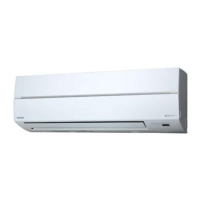
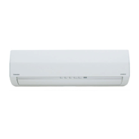
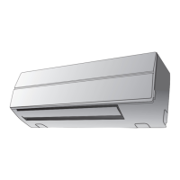
Provides diagrams and dimensions for the indoor unit's components.
Provides diagrams and dimensions for the outdoor unit's components.
Wiring diagram illustrating connections for models 10 and 13.
Wiring diagram illustrating connections for model 16.
Lists electrical parts and specifications for the indoor unit.
Lists electrical parts and specifications for the outdoor unit.
Illustrates the refrigerant flow for models 10 and 13.
Illustrates the refrigerant flow for model 16.
Provides operational data for cooling mode, including pressure and temperatures.
Provides operational data for heating mode, including pressure and temperatures.
Shows control logic and components for the indoor unit.
Illustrates control logic and components for the outdoor unit.
Describes the air conditioner's control system, roles, and communication.
Lists and briefly describes various operation modes like ECO, Temporary, etc.
Covers setting and cancelling the auto restart feature.
Describes remote controller parts and how to use its functions.
Illustrates the basic operation flow and control.
Explains the logic and control for cooling and heating operation modes.
Describes the logic and flow for AUTO operation mode.
Explains the logic and control for DRY operation mode.
Details indoor fan speed control in cooling operation.
Details indoor fan speed control in heating operation.
Explains outdoor fan speed control logic and tables.
Describes how cooling/heating capacity is adjusted by compressor speed.
Explains function to prevent inverter part damage by controlling current.
Protective control based on indoor heat exchanger temperature.
Describes defrost operation for heating mode.
Explains louver position, adjustment, and swing operations.
Describes the energy-saving ECO operation.
Explains temporary operation via reset button.
Control based on discharge temperature for error detection.
Describes control of refrigerant flow via PMV.
Explains the self-cleaning operation for hygiene.
Describes how to set remote control for multi-unit systems.
Describes the low-noise QUIET mode.
Explains the COMFORT SLEEP mode for energy saving.
Describes the automated one-touch comfort setting.
Explains the Hi-POWER mode for rapid cooling/heating.
Instructions on how to reset the filter indicator.
Step-by-step guide to enable the auto restart feature.
Steps to disable the auto restart feature.
Behavior during power failure when timer is active.
Identifies buttons and basic functions of the remote controller.
Describes operations like ONE-TOUCH, AUTO, COOL/HEAT/FAN.
Continues operation modes: DRY, Hi-POWER, ECO, TEMPORARY, TIMER.
Setting and operating preset preferences.
Setting auto restart after power failure.
Describes the quiet operation mode.
Explains comfort sleep mode for energy saving.
Setting sleep timer for operation.
Visual guide for unit placement and piping.
Lists parts needed for installation.
Details how to secure the outdoor unit with bolts.
Lists items supplied with the unit for installation.
Highlights new tools required for R410A systems.
Guidelines for choosing a suitable indoor unit location.
Instructions for drilling holes and mounting the installation plate.
Details electrical supply and wiring standards.
Procedure for wiring the connecting cable.
Instructions for routing pipes and drain hose.
Steps for attaching the drain cap and hose.
Steps for mounting the indoor unit onto the installation plate.
Proper drainage setup and precautions.
Guidelines for selecting a suitable outdoor unit location.
Procedure for draining water from the outdoor unit base.
Details on flaring and connecting refrigerant pipes.
Correct torque and procedure for tightening flare connections.
Steps for evacuating air from the refrigerant system.
Guidelines for handling packed valves.
Procedure for connecting the outdoor unit wiring.
How to check for gas leaks after installation.
Procedure to test the installed system.
How to enable the auto restart feature.
Setting remote controller for multiple indoor units.
Lists general steps for diagnosing issues.
Safety warnings for handling the new inverter.
Precautions and procedure for inspecting the outdoor unit controller.
Checks for normal power supply, voltage, and non-trouble operations.
Interpreting flashing LEDs for self-diagnosis.
Guide on how to use the remote for self-diagnosis.
Cautions during servicing and details of error check codes.
Lists various check codes and corresponding troubleshooting actions.
Troubleshooting steps for indoor unit issues.
Troubleshooting power-on issues for the indoor unit.
Diagnosing indoor fan motor issues in cooling operation.
Diagnosing indoor fan motor issues for model 16SKV2-E.
Diagnosing auto-rotation for DC fan motors.
Diagnosing auto-rotation for AC fan motors.
Steps to diagnose remote controller problems.
Troubleshooting wiring issues between indoor and outdoor units.
Procedures for checking key components like pulse motor valve.
Summarizes diagnosis steps for the inverter assembly.
Procedures for checking the indoor unit PC board.
Detailed check procedures for specific models.
Detailed check procedures for model 16.
Diagram of PC board and sensor resistance characteristics.
Checking procedures for indoor unit components like sensors and motors.
Checking procedures for outdoor unit components like compressor and motors.
Detailed checking methods for capacitors and converter modules.
Method to determine if the outdoor fan motor is good or bad.
General precautions and introduction to indoor unit parts replacement.
Procedure for removing and installing the front panel.
Procedure for replacing the electric parts box assembly.
Procedures for replacing the horizontal louver and evaporator.
Procedure for replacing the bearing.
Procedure for replacing the fan motor.
Procedure for replacing the cross flow fan.
Procedure for replacing the microcomputer.
General steps for disassembling and reassembling the outdoor unit.
Procedure for removing and installing the front cabinet.
Procedure for replacing the inverter assembly.
Procedure for replacing the control board assembly.
Procedure for replacing the side cabinets.
Procedure for replacing the outdoor fan motor.
Procedure for replacing the compressor.
Procedure for replacing the reactor.
Procedure for replacing the electronic expansion valve coil.
Procedure for replacing the fan guard.
Procedures for replacing various temperature sensors.
Detailed procedure for replacing temperature sensors.
Exploded view and parts list for the indoor unit.
Exploded view and parts list for the indoor unit.
Exploded view and parts list for the outdoor unit.
| Cooling Capacity | 4.5 kW |
|---|---|
| Heating Capacity | 5.4 kW |
| Seasonal Energy Efficiency Ratio (SEER) | 6.1 |
| Power Supply | 230V / 50Hz / 1Ph |
| Refrigerant | R410A |
| Weight (Indoor Unit) | 9 kg |
| Coefficient of Performance (COP) | 3.61 |
| Indoor Unit Weight | 9 kg |
| Type | Split Type Air Conditioner |
| Noise Level (Outdoor) | 50 dB(A) |