Do you have a question about the Toshiba RAS-24SKHP-ES2 and is the answer not in the manual?
| Brand | Toshiba |
|---|---|
| Model | RAS-24SKHP-ES2 |
| Category | Air Conditioner |
| Language | English |
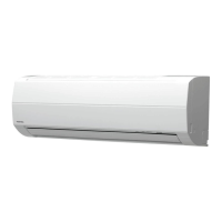
Detailed diagrams of the indoor unit's physical structure and dimensions.
Detailed diagrams of the outdoor unit's physical structure and dimensions.
Electrical wiring schematic for specific indoor and outdoor unit models.
Electrical wiring schematic for specific indoor and outdoor unit models.
Detailed specifications for indoor unit electrical components like sensors and motors.
Detailed specifications for outdoor unit electrical components like compressor and fan motor.
Detailed specifications for indoor unit electrical components like sensors and motors.
Detailed specifications for outdoor unit electrical components like compressor and fan motor.
Diagrams illustrating the refrigerant flow for specific cooling models.
Diagrams illustrating the refrigerant flow for specific heating/cooling models.
Block diagram showing the control logic for specific indoor/outdoor units.
Block diagram showing the control logic for specific indoor/outdoor units.
Details on remote control buttons, display indicators, and operations.
Overview of indoor and outdoor unit control logic and functions.
Explanation of various operating modes like Cooling, Dry, Heating, Auto.
Safety features like low-temp limit, high-temp limit, and defrost control.
Description of the automated one-touch comfort operation mode.
Explanation of the high power operation mode for rapid cooling/heating.
Explanation of the quiet operation mode for reduced noise levels.
Explanation of the energy-saving ECO operation mode.
Details on the comfort sleep mode for improved user comfort and energy saving.
Information on the filter check indicator and its reset procedure.
Instructions on how to set and use the auto restart feature after power failure.
Explanation of the self-cleaning function for maintaining unit cleanliness.
Critical safety precautions and warnings to follow during installation.
Visual guide and steps for installing indoor and outdoor units.
Lists of optional and accessory parts required for installation.
Detailed steps for installing the indoor unit, including mounting and wiring.
Detailed steps for installing the outdoor unit, including piping and wiring.
Procedures for gas leak testing, test operation, and controller setup.
General steps to follow for diagnosing and resolving issues.
Initial checks for power supply, wiring, and operation status.
Initial diagnosis based on symptoms, controller roles, and lamp indicators.
Using the remote controller to access service mode and check fault codes.
Diagnostic flowcharts for identifying defective internal parts.
Specific troubleshooting steps for common indoor unit failures.
Steps to troubleshoot issues related to interconnect and serial signal wiring.
Procedures for checking and diagnosing the indoor P.C. board.
Steps to diagnose and resolve problems with the remote control unit.
Step-by-step instructions for replacing internal components of the indoor unit.
Step-by-step instructions for replacing internal components of the outdoor unit.
Exploded view and part numbers for the indoor unit's components.
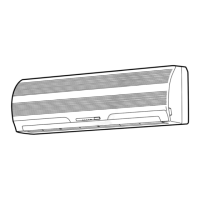
Visual breakdown of the indoor unit showing all assembled parts.
Visual breakdown of the outdoor unit for a specific model.
Visual breakdown of the outdoor unit for another specific model.