Do you have a question about the Toshiba RAS-25J2KVSG-ND and is the answer not in the manual?
Precautions for R32 refrigerant, installation, and servicing safety.
Details on unit dimensions, capacity, electrical specs, piping, and refrigerant.
Lists indoor unit accessories and optional installation parts.
Safety during installation/servicing and refrigerant piping installation guidelines.
Lists tools exclusive for R32 and interchangeable tools.
Details the steps and precautions for charging refrigerant.
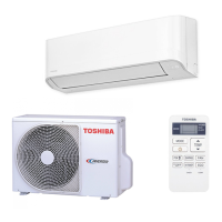
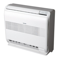
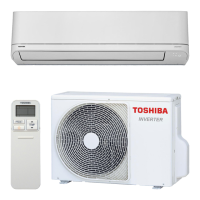
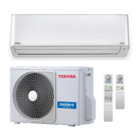
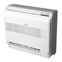
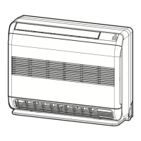
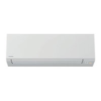
Diagrams and dimensions of indoor and outdoor unit components.
Lists electrical components for both units and their specifications.
Illustrates refrigerant flow and provides operational data based on conditions.
Shows control logic and components for indoor and outdoor units.
General overview of control system, roles of controllers, and command signals.
Covers basic, cooling, heating, AUTO, DRY, fan motor, louver, and special modes.
Explains remote control selection, Hi-POWER, timer, preset, and airflow functions.
Details auto restart function and remote control display indicators.
Operation of weekly timer, editing, deleting programs, and remote control indicators.
Explains Auto, Fireplace, 8°C Heating, Cooling/Heating/Fan Only, Dry, Hi-POWER, ECO, COMFORT SLEEP, HADA CARE.
Covers outdoor unit power selection, silent operation, and timer settings.
Explains preset operation and how to adjust airflow direction.
Explains the meaning of various indicators and symbols on the remote control display.
Illustrates unit placement and lists all installation parts.
Details tools required for R32 refrigerant and installation/servicing tools.
Specifies ideal locations for the indoor unit and how to mount the installation plate.
Covers piping, drain hose installation, and wired remote controller connection.
Specifies outdoor unit placement and precautions for cold regions.
Steps for connecting pipes, flaring, tightening, and performing evacuation.
Instructions for connecting power supply and wiring for indoor and outdoor units.
Covers gas leak testing, remote control A/B selection, test operation, and auto restart.
General troubleshooting procedures, precautions, and initial confirmation steps.
Interprets LED flashing codes and self-diagnosis via remote controller.
Flowcharts for diagnosing indoor unit issues like no power or fan motor problems.
Troubleshooting for wiring failures and outdoor unit stopping or not operating.
Procedures for checking main parts like pulse motor valve and temperature sensors.
Summarizes inverter diagnosis and checks for compressor winding resistance.
Precautions and procedures for checking the indoor unit's P.C. board and other parts.
Step-by-step procedures for checking various indoor unit components and their causes.
Diagram of the P.C. board layout and resistance characteristics of sensors.
Procedures for checking resistance values of indoor and outdoor unit components.
Details checking methods for electrolytic capacitors and converter modules.
Explains symptoms, causes, and methods to determine if the outdoor fan motor is faulty.
Procedures for replacing indoor unit parts like air filters and grilles.
Steps for removing and replacing the front panel and electric parts box assembly.
Procedures for replacing the fan motor and horizontal louver.
Steps to remove and reinstall the drain pan assembly and unit display.
Procedures for replacing the vertical louver assembly and cross flow fan.
Steps for replacing the heat exchanger and microcomputer.
Procedures for detaching outdoor unit parts and replacing the front cabinet.
Steps for safely replacing the inverter assembly, including discharging.
Procedures for disconnecting and replacing the control board assembly.
Steps for replacing side cabinets and the fan motor.
Procedures for replacing the compressor and reactor.
Steps for replacing the expansion valve coil and fan guard.
Instructions for installing and replacing various temperature sensors.
Diagram showing indoor unit parts and a corresponding parts list.
Diagram and parts list for specific internal components of the indoor unit.
Diagram showing outdoor unit parts and a corresponding parts list.
Diagram and parts list for specific internal components of the outdoor unit.
| Type | Split System |
|---|---|
| Cooling Capacity | 2.5 kW |
| Heating Capacity | 3.2 kW |
| Refrigerant | R32 |
| Noise Level (Indoor) | 21 dB(A) |
| Power Supply | 220-240V, 50Hz |
| Indoor Unit Net Weight | 9 kg |
| Outdoor Unit Net Weight | 23 kg |
| Noise Level (Indoor Unit) | 21 dB(A) |