Do you have a question about the Toshiba RAV-GM 801UT-E and is the answer not in the manual?
Detailed technical specifications for various indoor unit models including electrical characteristics and dimensions.
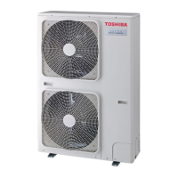
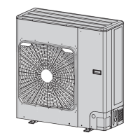
Detailed technical specifications for outdoor unit models including capacity, weight, and operating conditions.
Graphs showing operational characteristics based on temperature and current for different models.
External views and dimensions of the RAV-GP801AT* outdoor unit with component labeling.
External views and dimensions of the RAV-GP1101AT* and GP1401AT* outdoor units.
Dimensions and quantity for branch pipes used in twin systems.
Electrical wiring diagram for the RAV-GP801AT* outdoor unit control board.
Electrical wiring diagram for the RAV-GP1101AT* and GP1401AT* outdoor units.
List and specifications of electrical components used in the outdoor unit for different models.
Safety precautions and considerations for handling R32 refrigerant during installation and service.
Guidelines for selecting and processing piping materials for R32 systems.
Required tools for installation, servicing, and handling of R32 refrigerant.
Step-by-step instructions for recharging refrigerant into the system.
Materials, flux types, and methods for brazing pipes with R32.
Conditions and restrictions for reusing existing refrigerant piping for R32.
Guidelines and cautions for adding refrigerant to the system.
Overall safety measures and precautions specific to R32 refrigerant.
Essential safety warnings, including danger, caution, and prohibition notices.
Critical safety advice regarding the use of R32 refrigerant and potential accidents.
Comprehensive safety guidelines for installation and service procedures with R32.
Recommended materials and specifications for refrigerant piping.
List of specific tools required for R410A systems, applicable to R32.
List of common tools required for installation and service tasks.
Details of the outdoor unit's control board and component connections.
Overview of the air conditioner's primary control functions and logic.
How the outdoor fan speed is controlled based on temperature and taps.
Explanation of the defrost operation cycles and conditions.
Control strategy to protect the compressor from short cycling.
Control mechanism to limit compressor revolution based on current.
How heat sink temperature affects fan speed and compressor operation.
Adjusting current release values based on sensor readings.
Protection mechanism against over-current conditions for the compressor.
Control actions triggered by high-pressure or thermostat faults.
Control to manage high-pressure conditions by adjusting frequency.
Function for heating the compressor to prevent refrigerant stagnation.
General overview and initial checks for troubleshooting the unit.
Method for judging and identifying the location of troubles via indicators.
Troubleshooting steps for issues not indicated by specific check codes.
How to use the remote controller's service monitor for diagnostics.
Table of outdoor unit check codes and their corresponding causes.
Identification of failure modes and causes detected by the indoor unit.
Identification of failure modes and causes detected by the outdoor unit.
Troubleshooting communication failures between controllers and units.
Step-by-step procedures for diagnosing issues based on check codes.
Resistance characteristics for key temperature sensors.
Resistance characteristics for discharge and heat exchanger sensors.
Procedure to recall past trouble codes and history from the indoor unit.
Guide to using service switches SW01 and SW02 for diagnostics and settings.
Optional operations like peak-cut and night operation for the outdoor unit.
Steps for setting up unit addresses for proper system communication.
Configuration and definition of indoor unit addressing and group control.
Instructions for connecting the remote controller wiring.
Manual process for setting unit addresses using the remote controller.
Method to verify indoor unit addresses and their operational status.
Procedure for setting model switching and other configurations via jumpers.
Step-by-step guide for replacing the service P.C. board.
Overview of the steps involved in compressor replacement.
Reference to the detailed compressor replacement procedure in Section 13.
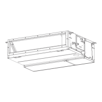
Detailed instructions for disassembling the RAV-GP801AT* outdoor unit components.
Steps to remove the front panel, top cover, and terminal cover.
Procedures for removing side cabinets and air-outlet cabinet.
Steps to detach the control P.C. board and associated components.
Procedures for removing the reactor and fan motor.
Steps for removing the compressor and its electrical leads.
Procedures for detaching the PMV and 4-way valve coils.
Instructions for removing the fan guard.
Detailed instructions for disassembling the RAV-GP1101AT* and GP1401AT* outdoor units.
Steps to remove the front panel, top cover, and terminal cover.
Procedures for removing side cabinets and air-outlet cabinet.
Steps to detach the control P.C. board and associated components.
Procedures for removing the reactor and fan motor.
Steps for removing the compressor and its electrical leads.
Procedures for detaching the PMV and 4-way valve coils.
Instructions for removing the fan guard.
Visual breakdown and part number list for the outdoor unit assembly.
Visual breakdown and part number list for the inverter assembly.
| Brand | Toshiba |
|---|---|
| Model | RAV-GM 801UT-E |
| Category | Air Conditioner |
| Language | English |