Why is the indoor fan not rotating on my Toshiba Air Conditioner?
- LLuke MorrisonAug 1, 2025
The indoor fan of your Toshiba Air Conditioner may not rotate if the cool air discharge prevention control is active during heating operation.
Why is the indoor fan not rotating on my Toshiba Air Conditioner?
The indoor fan of your Toshiba Air Conditioner may not rotate if the cool air discharge prevention control is active during heating operation.
Defines the qualifications and knowledge required for service personnel.
Explains danger, warning, and caution symbols used in the manual.
Explains prohibition, mandatory, and caution marks.
Describes warning symbols found on the unit itself.
Details critical safety instructions to prevent immediate death or serious injury.
Outlines potential risks of serious injury or death from product failure due to incorrect work.
Provides general safety advice for installation, servicing, and working at heights.
Precautions to prevent fire hazards when working with R32 refrigerant.
Guidelines for proper ventilation when handling refrigerant gas leaks.
Cautions regarding refrigerant type, mixing, charging, and recovery.
Safety measures for component assembly and wire connections.
Procedure to check insulation resistance after repair work.
Mandatory actions and precautions during installation.
Actions strictly forbidden during installation to prevent hazards.
Importance of wearing gloves for protection against parts and injury.
Checks to perform after welding work, especially for refrigerant leaks.
Guidelines for qualified personnel to relocate the air conditioner safely.
Essential safety items and precautions for R32 installation and servicing.
Details on copper pipe selection, thickness, and flare nut requirements for R32.
Describes flare and socket joints used for copper pipes.
Lists common tools needed for installation and operational checks.
Specifies the required power supply voltage and frequency for the outdoor unit.
Details on compressor type, motor, refrigerant charge, and control.
Specifies length and height difference limits for connecting pipes.
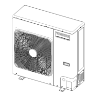
Physical dimensions of the outdoor unit (Height, Width, Depth).
Type of heat exchanger used in the outdoor unit.
Details on fan type, motor power, and air flow.
Gas and liquid side pipe diameters.
Measured sound pressure levels for cooling and heating.
Measured sound power levels for cooling and heating.
Allowed outdoor air temperature range for cooling operation.
Allowed outdoor air temperature range for heating operation.
Graphs showing current vs. compressor speed and capacity ratio vs. outdoor temperature.
Graphs showing current vs. compressor speed and capacity ratio vs. outdoor temperature.
Indicates specific notes related to external views or components.
Table specifying refrigerant pipe outer diameters for the indoor unit.
Table showing pressure values for cooling and heating modes.
Table showing pipe surface temperatures for cooling and heating modes.
Illustration showing the layout of electrical components and connections.
Table listing electrical components with their types and specifications.
Crucial safety precautions for installing and servicing R32 refrigerant systems.
Guidelines for installing refrigerant piping systems using R32.
Minimum joint thickness requirements for socket joints.
Diagram illustrating dimensions for flare processing.
Dimensions for R32 flare connections and nuts.
Dimensions for R22 flare connections and nuts.
Reference values for tightening torque of flare connections for R32.
Step-by-step guide for recharging refrigerant into the system.
Diagram showing the setup for refrigerant charging.
Details on silver brazing filler, phosphor bronze filler, and low temperature filler.
Explains the necessity, characteristics, and types of flux for brazing.
Diagram illustrating the method to prevent oxidation during brazing.
Checks required for reusing existing refrigerant pipes.
Cases where existing pipes should not be reused and require replacement.
Disclaimer regarding company confirmation and general applicability.
Guidelines for reusing branching pipes in simultaneous operation systems.
Methods for curing pipes when units are disconnected for extended periods.
Steps and checks related to the installation of existing piping.
Specific warnings and replacement advice when using existing pipes.
Procedure for recovering refrigerant using recovery equipment.
Guidelines and restrictions on adding refrigerant to the system.
Safety guidelines for recovering refrigerant from systems.
Safety precautions for decommissioning equipment and recovering refrigerant.
Requirements for labeling decommissioned equipment containing flammable refrigerant.
Details on how the Pulse Modulating Valve is controlled by sensors.
Notes on sensor troubles and compressor protection checks.
How the system controls compressor frequency based on discharge temperature.
How the outdoor fan speed is controlled based on various sensors and conditions.
Specifics of cooling fan speed control based on temperature and other factors.
Function of coil heating to prevent refrigerant stagnation in the compressor.
Control to prevent electronic part troubles by adjusting current release values.
System response to abnormal current detection, including compressor stop and restart.
Control to restrain abnormal high pressure by managing operation frequency.
How the compressor operation terminates when the high-pressure switch operates.
Compressor stop mechanism when the case thermostat operates, triggering H04 error.
Identifies connectors and components on the WP-507 circuit board.
Explains the function of the jumper for model switch selection.
Specifies the grounding method for the circuit board.
Overview of troubleshooting steps and initial checks for wired remote controllers.
General procedure for diagnosing and resolving troubles.
General procedure for diagnosing and resolving troubles for wireless remote controllers.
Method to determine if a problem is in the indoor or outdoor unit using lamp indications.
Lists specific causes of trouble for various check codes.
Procedure to enter and use the service monitoring mode on the RBC-AMT controller.
Procedure to enter and use the monitoring function on the RBC-ASCU11 controller.
Lists data codes for monitoring outdoor unit parameters like temperature and current.
Indicates the location of the defect identified by check codes.
Describes the detection status (e.g., sensor error, communication error).
Explains the meaning of various error codes and their causes.
Lists indications on the remote controller for troubleshooting.
Explains sensor lamp status for troubleshooting.
Details the diagnostic functions for detecting indoor unit failures.
Provides diagnosis and corrective actions for specific indoor unit failure codes.
Lists operational causes for outdoor unit failures.
Describes the conditions under which outdoor unit failures are detected.
Provides diagnosis and corrective actions for outdoor unit failure codes.
Lists operational causes for indoor unit failures.
Describes conditions indicating indoor unit failures.
Diagnosis and corrective actions for specific indoor unit failure codes.
Lists operational causes for controller communication failures.
Conditions indicating controller communication failures.
Diagnosis and measures for controller communication issues.
Explains the meaning of LED indicators on the outdoor PC board.
Describes the functionality of service switches SW01 and SW02.
Steps to check LED displays on the outdoor PC board for troubleshooting.
Diagnostic procedure for E04 communication errors.
Diagnostic procedure for F06 TE sensor errors.
Diagnostic procedure for F07 TL sensor errors.
Diagnostic procedure for F12 TS sensor errors.
Diagnostic procedure for F08 TO sensor errors.
Diagnostic procedure for F13 TH sensor errors.
Diagnostic procedure for F31 EEPROM errors.
Diagnostic procedure for H02 compressor lock errors.
Diagnostic procedure for H04 case thermostat errors.
Diagnostic procedure for L29 communication errors between MCUs.
Diagnostic procedure for P03 discharge temperature errors.
Diagnostic procedure for P05 power supply issues.
Diagnostic procedure for P20 high pressure protective operations.
Diagnostic procedure for H04 case thermostat errors.
Diagnostic procedure for P07 heat sink overheat errors.
Steps to check temperature sensors in relation to gas leak detection.
Using service switches to check 4-way valve operation and troubleshoot issues.
Specific troubleshooting steps for heating operation issues.
Specific troubleshooting steps for cooling operation issues.
Procedure to check outdoor fan operation using service switches.
Detailed steps for performing the outdoor fan check.
Diagnostic procedure for P29 position detection circuit errors.
Resistance values for various temperature sensors at different temperatures.
Resistance values for TD and TL sensors.
Procedure to measure the resistance value of compressor windings.
Procedure to measure the resistance value of outdoor fan motor windings.
Procedure to measure the resistance value of the 3-way valve coil.
How to troubleshoot using check codes and trouble history displayed on the remote controller.
General procedure for diagnosing and resolving troubles via remote controller.
Warning about erasing the entire trouble history of the indoor unit.
Procedure to check troubleshooting history on the RBC-ASCU11 controller.
Warning about using the menu button in history mode.
Guide to interpreting 7-segment display symbols and alphanumerics.
How setup ranges are reflected on the remote controller in group control.
Procedure for setting up addresses for group control operation.
Steps involved in the automatic address judgment for group control.
Steps taken during initial communication after power-on.
Important cautions to observe during test runs for group control.
How to use service switches SW01 and SW02 for various operations.
Explains the meaning of LED indicators on the outdoor PC board.
Procedure for refrigerant recovery operation (pump down).
How to configure various settings using service switches.
Procedure to confirm if settings have been applied correctly.
How to select cooling-only or heating-only operation mode.
Method to set or cancel cooling/heating only operation modes.
Shows the initial state of LED displays for service switches.
LED display pattern for procedure step 2.
LED display pattern for procedure step 3.
LED display pattern for procedure step 4.
LED display pattern for procedure step 5.
LED display for canceling settings (Procedure 2).
LED display for canceling settings (Procedure 3).
LED display for canceling settings (Procedure 4).
Table showing how to switch LED displays for various parameters.
Step-by-step guide to switch LED displays using service switches.
Shows current errors indicated by LED display and wired remote controller codes.
Shows the latest recorded errors, including current ones.
Displays sensor values, current, and frequency via LED patterns.
Details special operations like refrigerant recovery and PMV control.
Procedure for performing refrigerant recovery operation.
Operation to fully open the Pulse Modulating Valve.
Operation to fully close the Pulse Modulating Valve.
Operation to set the PMV to a middle opening position.
Command to perform a trial heating operation for indoor units.
Command to perform a trial cooling operation for indoor units.
Operation to force the fan motor to run.
Operation related to the self-preservation valve suck function.
Operation related to the self-preservation valve secession function.
Control to reduce capacity during peak demand periods.
Function to reduce operation noise during nighttime.
Control for compressor operation output, turning on a voltage-free contact.
Steps for setting up unit addresses for operation and group control.
Details on automatic address setup completion with power-ON.
Information on necessary address data for test run operations.
Definitions of terms related to indoor unit and group addresses.
Diagrams illustrating single unit and group system configurations.
Example of a single group operation setup with multiple indoor units.
Example of automatic address setup for a single outdoor unit.
Describes the header unit's function in automatic address setup.
Describes the follower unit's function in automatic address setup.
Example of automatic address setup for a single outdoor unit.
Example of automatic address setup for group operation with multiple units.
Diagrams illustrating wiring for single and simultaneous twin systems.
Wiring details for a single system setup.
Wiring details for simultaneous twin system setups.
Procedure for manual address setting using the remote controller.
Example wiring for manual address setting with two refrigerant lines.
Steps to set the line (system) address using the remote controller.
Steps to set the group address (individual, header, follower).
Procedure for manual address setting using the RBC-ASCU11 controller.
How to confirm indoor unit addresses and their sequence.
How to confirm unit addresses for individual or group-controlled units.
Procedure to check unit numbers in a group, activating fans and louvers.
Procedure to check unit numbers using the RBC-ASCU11 controller.
Lists parts and objects to be checked during maintenance.
Details the specific checks for each part during maintenance.
Describes the maintenance actions to be performed for each part.
Step-by-step instructions for assembling the replacement P.C. board.
An overview of the steps involved in exchanging the compressor.
Reference to further details on compressor exchange in Section 13.
Steps for detaching major components like the front panel and top plate.
Steps for attaching major components after servicing.
Steps for removing the side cabinet, including inverter assembly.
Detailed steps for detaching various electrical parts and connectors.
Important note on safely disengaging connectors.
Procedure to remove the ASM-INV from the back panel.
Steps to disconnect all connectors from the ASM-PCB(CDB).
Procedure to remove the ASM-PCB(CDB) from its support spacers.
Steps for attaching P.C. boards and other components after replacement.
Procedure to remove screws from the ASM-S-COVER-NF.
Steps to remove faston connectors from the main terminal.
Procedure to remove all connectors from the ASM-PCB(NF).
Steps to remove screws and the ASM-PCB(NF) from spacers.
Procedure to remove ASM-S-BASE-CDB from ASM-INV-SUB.
Steps to remove connectors and screws from the assembly.
Procedure to remove the ASM-PCB(IPDU) from support spacers.
Identifies the ASM-PCB(IPDU) component.
Important points to consider when assembling the fan motor.
Caution regarding fixing the fan motor lead to prevent contact.
Note about reusing the clamp filter when replacing the fan motor.
Steps for removing a defective compressor, including piping and sensor disconnection.
Safety warning when using a burner to remove piping due to fire risk.
Caution to avoid flames affecting the 4-way valve and PMV.
Warning about the weight of the compressor and the need for two workers.
Steps for mounting the new compressor, including sensor and pipe lead management.
Important notes regarding sensor and pipe lead placement during mounting.
Steps for vacuuming the system after compressor installation.
Note regarding PMV operation during vacuuming.
Method for forcing the PMV to fully open.
Steps for charging the specified amount of refrigerant.
Procedure for removing and attaching the PMV coil.
Steps for removing the fan guard.
Steps for attaching the fan guard.
Caution to check that all hooking claws are fixed correctly.
Diagram showing exploded views of outdoor unit components.
List of parts for the RAV-GV model, specifying quantities.
List of components within the inverter assembly.
Information on concentration limits for refrigerant gas in rooms.
| Brand | Toshiba |
|---|---|
| Model | RAV-GV1601AT8P-E |
| Category | Air Conditioner |
| Language | English |


