Toshiba
4-1
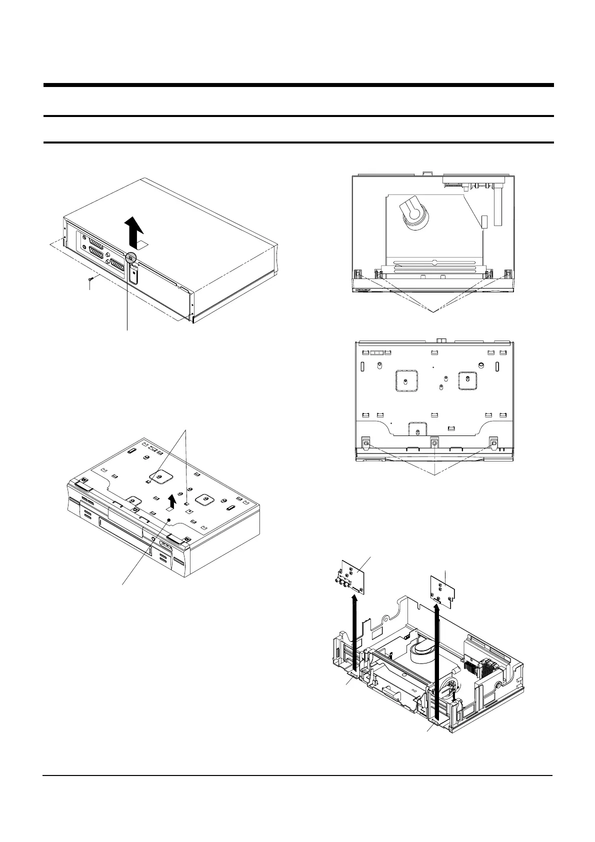
4. Disassembly and Reassembly
4-1 Cabinet Assembly
4-1-1 Cabinet Top Removal
ΠREMOVE 2 SCREWS
´ Lift up the Cabinet Top in the direction of
arrow by releasing the Hook.
Fig. 4-1 Cabinet Top Removal
4-1-3 Ass’y Front Panel Removal
Fig. 4-3 Ass’y Front Panel Removal
ΠRELEASE 4 HOOKS
´ RELEASE 3 HOOKS
(Top View)
(Bottom View)
4-1-4 Ass’y Function PCB Removal
Disconnect the CN708/CN710 from the Ass'y PCB-Main
and then lift the Ass'y Function PCB up.
CN708
CN710
Fig. 4-4 Ass’y Function PCB Removal
ΠRELEASE 2 SNAPFITS
´ Lift up the Bottom Cover in the direction of arrow.
4-1-2 Bottom Cover Removal
Fig. 4-2 Bottom Cover Removal