Do you have a question about the Toshiba V-E78 and is the answer not in the manual?
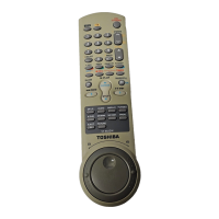
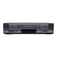
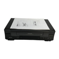
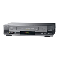
Explains the operation of the VCR's front panel, rear panel, and remote control.
Details the VCR's display indicators and provides guidance on connecting the VCR.
Instructions for removing the top and bottom covers and the front panel assembly.
Details tape transport system adjustments and locations for optimal performance.
Procedure for adjusting the head switching point for optimal signal.
Instructions for setting NVRAM options, necessary after component replacement.
Diagram illustrating the packaging components of the VCR unit.
Exploded view showing the main internal assemblies and components of the VCR.
Detailed exploded view of mechanical parts located on the top side of the VCR.
Detailed exploded view of mechanical parts located on the bottom side of the VCR.
Schematic diagram of the main printed circuit board (PCB) for the VCR.
Schematic diagram illustrating the function of specific PCB sections.
Diagram showing the block identification of the VCR's main PCB.
Schematic diagram of the Switched Mode Power Supply (SMPS) section.
Schematic diagram detailing the power supply circuits.
Schematic for system control, servo, and display functions.
Schematic diagram for audio and video signal processing.
Schematic diagram for the Hi-Fi audio circuitry.
Schematic diagram of the TM-Block section.
Schematic diagram for A2/NICAM audio processing.
Schematic diagram for On-Screen Display (OSD), VPS, and PDC functions.
Schematic diagram illustrating the VCR's input and output connections.
Schematic diagram of the F-AV assembly.