Do you have a question about the Tosibox 610 and is the answer not in the manual?
Shows Nodes matched to the Key and network devices connected to them. Provides options for more details and connections.
Visual cues indicating Node's internet and remote connection status to the Key.
Instructions for mounting the DIN-Rail adapter to the device housing using provided screws.
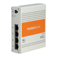
Illustrations of TOSIBOX 610, 650, and 670/675 models.
Diagram showing power and ground wire connections for the device.
Statement of compliance with EU Directive 2014/53/EU for radio equipment.
Information regarding compliance with FCC rules and potential interference.
Information on where to find user manuals and download software updates.
The TOSIBOX® 600 Series, including models 610, 650, 670, and 675, offers a secure and straightforward solution for remote access and network management. This Quick Start Guide outlines the essential steps for setting up and utilizing these devices, focusing on their core function as a secure remote access point.
The primary function of the TOSIBOX® Node is to establish a secure, encrypted remote connection between a TOSIBOX® Key and a local network. This allows users to access devices and systems within the Node's network from anywhere with an internet connection, effectively creating a private, secure tunnel. The Node acts as a central point for this secure connection, ensuring data integrity and confidentiality. It supports various internet connectivity options, including Ethernet and wireless (LTE Modem or WLAN), making it adaptable to different deployment scenarios. The matching process between the Node and a Key is a one-time operation that securely links the two devices, enabling subsequent remote access. Once matched, the Key can be used to manage and access multiple Nodes and the devices connected to them. The system is designed for ease of use, minimizing complex network configurations, and providing a plug-and-play experience for secure remote access.
The TOSIBOX® Node offers several features designed to simplify its deployment and daily use:
Maintaining the TOSIBOX® Node involves ensuring its software is up-to-date and its physical components are correctly installed:
| Model | Tosibox 610 |
|---|---|
| Category | Network Hardware |
| Power Supply | 12-48 V DC |
| Operating Temperature | -20°C to +60°C |
| Humidity | 5% to 95% non-condensing |
| Firewall Throughput | 100 Mbps |
| VPN Throughput | 10 Mbps |
| Form Factor | DIN Rail Mountable |
| Connectivity | Ethernet, Wi-Fi |
| Ports | 1 x USB |
| Storage Temperature | -40°C to +70°C |
| Mobile Connectivity | 4G LTE (optional) |
| Security | Firewall |
| Compatibility | Tosibox Lock |