EasyManua.ls Logo

TOTALINE P102-12 - User Manual

TOTALINE P102-12
12 pages
Print Icon
To Next Page IconTo Next Page
Loading...
Manufacturer reserves the right to
discontinue, or change at any time,
specifications or designs without notice
and without incurring obligations.
REPLACEMENT COMPONENTS DIVISION LITERATURE NUMBER P102-2SI
© CARRIER CORPORATION 2002 3/02 REPLACES: EAC-50SI
PRINTED IN U.S.A. CATALOG NUMBER 570-476
Part Numbers: P102-12, P102-14A, P102-14B, P102-20
IF YOU NEED HELP call toll free: 1-800-267-8305
CONTENTS
SAFETY CONSIDERATIONS
. . . . . . . . . . . . . . . . . . . . . . 1
GENERAL
. . . . . . . . . . . . . . . . . . . . . . . . . . . . . . . . . . . . . . . . 1
COMPONENTS
. . . . . . . . . . . . . . . . . . . . . . . . . . . . . . . . 1,2
Cabinet
. . . . . . . . . . . . . . . . . . . . . . . . . . . . . . . . . . . . . . . . . . . 1
Power Box
. . . . . . . . . . . . . . . . . . . . . . . . . . . . . . . . . . . . . . . 2
Air Proving Switch (APS)
. . . . . . . . . . . . . . . . . . . . . . . . . 2
High Voltage Tray
. . . . . . . . . . . . . . . . . . . . . . . . . . . . . . . . . 2
Collecting Cells
. . . . . . . . . . . . . . . . . . . . . . . . . . . . . . . . . . 2
Prefilters
. . . . . . . . . . . . . . . . . . . . . . . . . . . . . . . . . . . . . . . . . 2
Carbon Filters
. . . . . . . . . . . . . . . . . . . . . . . . . . . . . . . . . . . . 2
INSTALLATION
. . . . . . . . . . . . . . . . . . . . . . . . . . . . . . . . . 2-4
Location
. . . . . . . . . . . . . . . . . . . . . . . . . . . . . . . . . . . . . . . . . 2
Electronic Air Cleaner Installation
. . . . . . . . . . . . . . . . 2
Wiring
. . . . . . . . . . . . . . . . . . . . . . . . . . . . . . . . . . . . . . . . . . . . 4
SYSTEM CHECK
. . . . . . . . . . . . . . . . . . . . . . . . . . . . . . . . . 5
OPERATION
. . . . . . . . . . . . . . . . . . . . . . . . . . . . . . . . . . . . . . 5
Ozone
. . . . . . . . . . . . . . . . . . . . . . . . . . . . . . . . . . . . . . . . . . . . 5
Dust
. . . . . . . . . . . . . . . . . . . . . . . . . . . . . . . . . . . . . . . . . . . . . 5
MAINTENANCE
. . . . . . . . . . . . . . . . . . . . . . . . . . . . . . . . . . 5
Cell and Prefilter Cleaning
. . . . . . . . . . . . . . . . . . . . . . . 5
Carbon Filter Replacement
. . . . . . . . . . . . . . . . . . . . . . . 5
SERVICE
. . . . . . . . . . . . . . . . . . . . . . . . . . . . . . . . . . . . . . . 5-9
Testing Air Proving Switch (APS)
. . . . . . . . . . . . . . . . . 5
Replacing an Air Proving Switch (APS)
. . . . . . . . . . . 6
Testing for High Voltage at Power Board
. . . . . . . . . 6
Replacing Performance Light
. . . . . . . . . . . . . . . . . . . . 6
Replacing a Power Board
. . . . . . . . . . . . . . . . . . . . . . . . 6
Testing the 24-V Transformer
. . . . . . . . . . . . . . . . . . . . . 6
Replacing the 24-V Transformer
. . . . . . . . . . . . . . . . . . 7
Testing Voltage of Power Board
. . . . . . . . . . . . . . . . . . 7
Testing Cell for Bad Contacts
. . . . . . . . . . . . . . . . . . . . 8
Removing Power Box
. . . . . . . . . . . . . . . . . . . . . . . . . . . . 8
Removal of High Voltage Contact Tray
. . . . . . . . . . . . 8
Replacing a Tungsten Ionizing Wire
. . . . . . . . . . . . . . 9
TROUBLESHOOTING
. . . . . . . . . . . . . . . . . . . . . . . . . . . . 10
SAFETY CONSIDERATIONS
Read and follow manufacturer instructions carefully. Fol-
low all local electrical codes during installation. All wiring
must conform to local and national electrical codes. Improper
wiring or installation may damage air cleaner.
Recognize safety information. This is the safety alert sym-
bol . When the safety alert symbol is present on equipment
or in the instruction manual, be alert to the potential for person-
al injury.
Understand the signal words DANGER, WARNING, and
CAUTION. These words are used with the safety alert symbol.
DANGER identifies the most serious hazards which will result
in severe personal injury or death. WARNING signifies a haz-
ard which could result in personal injury or death. CAUTION
is used to identify unsafe practices which would result in minor
personal injury or property damage.
Installation and servicing of air-conditioning equipment can
be hazardous due to system pressure and electrical compo-
nents. Only trained and qualified service personnel should
install, repair, or service air-conditioning equipment.
Untrained personnel can perform the basic maintenance
functions of cleaning and replacing filters. All other operations
should be performed by trained service personnel. When work-
ing on air-conditioning equipment, observe precautions in the
literature, tags and labels attached to the unit, and other safety
precautions that may apply.
Follow all safety codes. Wear safety glasses and work
gloves.
GENERAL
The electronic air cleaner is designed to remove atmospher-
ic and household dust, pollen, mold spores, bacteria, insecticide
dust, animal dander, coal dust, cooking smoke and grease, and
tobacco smoke particles down to 0.01 micron.
First the prefilter removes all large visible particles such as
lint or hair. Then the electronic air cleaner ionizes the particles
in the air (the particles are given a strong positive electrical
charge). The particles are then attracted to grounded plates and
collected. Pollutants are held onto the plates like a magnet until
cleaning when they are washed away. Optional carbon filter(s)
then remove the odors from the air.
The electronic air cleaner is available in 4 different models
and 3 different airflow capacities: 1200, 1400, and 2000 cfm.
See Table 1. The electronic air cleaner is adaptable to all
residential forced air furnace or cooling systems. It must be
installed in the return air duct, as close to the blower compart-
ment as possible. This location provides the most even airflow
across the collecting cells and allows the electronic air cleaner
to keep the system motor and blower clean.
Regular maintenance (cleaning of cells and filters) is
required by the home owner.
COMPONENTS
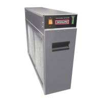
See Fig. 1 for a description of the electronic air cleaner.
Cabinet —
The cabinet is constructed of heavy gage galva-
nized steel. Holes are provided in the cabinet for easy mounting
in the ductwork or air-handling equipment. See Fig. 2 for cabi-
net dimensions.
IMPORTANT: Read entire instructions before install-
ing the air cleaner.
Before beginning any installation or modification, be cer-
tain that the main line electrical disconnect switch is in the
OFF position. Electric shock could result. Tag disconnect
switch with suitable warning labels.
INSTALLATION,
OPERATION, AND
MAINTENANCE
INSTRUCTIONS
Residential Duct Mount
Electronic Air Cleaner

Questions and Answers

  • J
    Jane SmithAug 15, 2025
    What to do if my TOTALINE Air Cleaner cells are arcing excessively?
    • C
      Charles TorresAug 15, 2025
      If your TOTALINE Air Cleaner cells are arcing excessively, it could be due to several reasons: * Cells are wet from washing: Allow cells to dry completely. * Particle lodged in cell or broken ionizing wire: Wash the cell, shake any particles out, and replace the wire if necessary. * Ducts were not cleaned prior to installation: Clean the ducts. * Cell plates are bent: Remove cells and adjust to original spacing using needle nose pliers. * Voltage is too high: Adjust the high voltage potentiometer on the power board counterclockwise. * Humidifier leaking: Repair the humidifier or move it to a different location if possible.
  • J
    James UnderwoodAug 18, 2025
    How to get rid of ozone odor from TOTALINE P102-12 Air Cleaner?
    • D
      douglasleblancAug 18, 2025
      If you notice an ozone odor from your TOTALINE Air Cleaner, here's what might be causing it and how to address it: * Cell plates are bent: Straighten them with needle nose pliers. * Loose or broken ionizing wires: Replace the wires. * Dirty cells: Wash the cells. * Air switch not activated, or electronic air cleaner wired incorrectly: Check operation and wiring of air switch and electronic air cleaner. * Incoming voltage is higher than 120 v: Adjust the high voltage potentiometer counterclockwise on the power board. * Air cleaner is oversized for house: Use correct size of electronic air cleaner. * Home is extremely dry: Repair or install central humidifier.
  • P
    Paul HermanAug 21, 2025
    Why my TOTALINE P102-12 isn't working and both lights are off?
    • J
      Joshua ButlerAug 21, 2025
      If your TOTALINE Air Cleaner isn't functioning and both the power and performance indicator lights are off, here are some possible causes and solutions: * Fan is not on: Turn furnace fan on. * Wiring improperly connected: Check wiring. * Defective power switch: Check power switch for continuity with multimeter. Replace if defective. * Defective safety interlock: Remove door and press safety interlock with a screwdriver. If lights come on, bend interlock lever towards front and close door. * Power (120 v) is not provided to device: Check power wiring with multimeter.
  • K
    Kenneth JonesAug 25, 2025
    What to do if TOTALINE P102-12 Air Cleaner cells are not collecting dirt?
    • N
      Nathan MitchellAug 26, 2025
      If the cells in your TOTALINE Air Cleaner aren't collecting dirt, consider the following: * Arrow on cell(s) not pointing towards fan blower: Reposition cells. * Furnace fan is on ‘‘Automatic’’ setting: Use ‘‘Fan On’’ furnace fan setting for continuous fan operation. * Not enough voltage on collecting cells: Adjust high voltage potentiometer clockwise on power board.
  • M
    Matthew TorresAug 28, 2025
    Why is my TOTALINE P102-12 arcing at the top of the cell?
    • K
      Kevin JonesAug 28, 2025
      If your TOTALINE Air Cleaner is arcing excessively at the top of the cell near the copper contacts, the cause might be that the contacts on the high voltage tray are broken or bent upward. If possible, pull down contacts with needle nose pliers or remove high voltage tray and replace contacts.
  • B
    Brenda LeachSep 4, 2025
    Why TOTALINE P102-12 Air Cleaner cell makes hissing noise or causes radio interference?
    • C
      Christopher HowellSep 4, 2025
      If your TOTALINE Air Cleaner cell is making a loud hissing noise or causing radio interference, it could be due to: * Internal cell contacts are not touching plates: Test contact and repair. * Copper contacts on high voltage tray not making good connection on cell: With needle-nose pliers, gently pull contacts down or replace contacts.
  • T
    Teresa OwenSep 7, 2025
    Why is there more dust after installing TOTALINE P102-12?
    • I
      iwhiteSep 7, 2025
      If you notice more dust after installing your TOTALINE Air Cleaner, consider these possibilities: * Lint dust too heavy to remain airborne: Keep fan running continuously. Ensure that return air grilles are not obstructed. * Gaps around electronic air cleaner: Seal or use duct tape around electronic air cleaner cabinet.
  • M
    Miguel GreenSep 12, 2025
    What if the power light is off but the performance indicator light is on in my TOTALINE P102-12?
    • S
      Stephanie YoungSep 12, 2025
      If the power light is off, but the performance indicator light is on for your TOTALINE Air Cleaner, the cause may be a defective power light. Replace the power switch.
  • D
    Daniel RobertsDec 1, 2025
    What to do if power light is on but performance indicator light is off on TOTALINE P102-12?
    • J
      Juan RodriguezDec 1, 2025
      If the power light is on but the performance indicator light is off on your TOTALINE Air Cleaner, here are potential causes and solutions: * Short in cells: Remove wire or wire fragments, spring and S-hook. Replace. Shake large particles out or wash cell. Allow cells to dry completely. Replace end plate insulator. Straighten plates with pliers. * Defective performance indicator light: Determine whether high voltage is present by testing power box. If present, replace indicator light. * Defective power board: Adjust high voltage potentiometer on power board clockwise. If high voltage is not present, replace power board. * Air proving switch sensor is burnt out: Remove power box and connect with 120 v. Lightly blow on air switch at the bottom of power box. If light does not come on,...

Overview

The Totaline Gold Residential Duct Mount Electronic Air Cleaner is designed to remove atmospheric and household dust, pollen, mold spores, bacteria, insecticide dust, animal dander, coal dust, cooking smoke and grease, and tobacco smoke particles down to 0.01 micron. It is adaptable to all residential forced air furnace or cooling systems and must be installed in the return air duct, as close to the blower compartment as possible, to ensure even airflow and keep the system motor and blower clean.

The air cleaner operates in stages: first, prefilters remove large visible particles like lint or hair. Then, the electronic air cleaner ionizes the remaining particles, giving them a strong positive electrical charge. These charged particles are then attracted to and collected on grounded plates, held like a magnet until cleaning. Optional carbon filters are available to remove odors from the air.

Important Technical Specifications:

The electronic air cleaner is available in four models with varying airflow capacities and duct sizes:

  • P102-12:

    • House Size Area: < 2400 ft² (< 222.96 m²)
    • Airflow: up to 1200 CFM (up to 2039 m³/hr)
    • Duct Size: 16 x 20 in. (405 x 510 mm)
    • Unit Weight: 28 lbs (12.9 kg)
    • Input Voltage: 120 V 60 Hz
    • Power Consumption: 30 Watts
    • Options Available: Activated Carbon Filters
  • P102-14A:

    • House Size Area: < 3000 ft² (< 278.70 m²)
    • Airflow: up to 1400 CFM (up to 2379 m³/hr)
    • Duct Size: 16 x 25 in. (405 x 635 mm)
    • Unit Weight: 30 lbs (13.5 kg)
    • Input Voltage: 120 V 60 Hz
    • Power Consumption: 30 Watts
    • Options Available: Activated Carbon Filters
  • P102-14B:

    • House Size Area: 2400-3000 ft² (222.96-278.70 m²)
    • Airflow: up to 1400 CFM (up to 2379 m³/hr)
    • Duct Size: 20 x 20 in. (510 x 510 mm)
    • Unit Weight: 33 lbs (15.3 kg)
    • Input Voltage: 120 V 60 Hz
    • Power Consumption: 30 Watts
    • Options Available: Activated Carbon Filters
  • P102-20:

    • House Size Area: > 3000 ft² (> 278.70 m²)
    • Airflow: up to 2000 CFM (up to 3398 m³/hr)
    • Duct Size: 20 x 25 in. (510 x 635 mm)
    • Unit Weight: 38 lbs (17.5 kg)
    • Input Voltage: 120 V 60 Hz
    • Power Consumption: 30 Watts
    • Options Available: Activated Carbon Filters

The device components include a heavy-gauge galvanized steel cabinet, a removable power box, an Air Proving Switch (APS), a high voltage tray, collecting cells, prefilters, and optional carbon filters. The power box houses the power switch, performance indicator light, safety interlock switch, high voltage power board, and the APS. The high voltage tray contains contacts and wires for supplying high voltage to the collecting cells, which consist of an ionizing section and a plate section. Prefilters are aluminum mesh, and carbon filters are used for odor removal.

Usage Features:

The electronic air cleaner operates only when the furnace fan is running, as the Air Proving Switch (APS) detects airflow and energizes the unit. For optimal performance, the heating/cooling system fan should run continuously, preferably on low speed. Furniture or carpets should not block return air grilles to ensure free airflow to the furnace.

Upon initial installation, some arcing or snapping sounds and a slight odor of ozone may be noticeable. This is normal and typically disappears within about two weeks as the collecting cells become smoother. The unit emits less than 0.005 ppm of ozone, which can be minimized with proper humidification in extremely dry environments. After installation, some white dust may still be visible on surfaces, as heavy particles like lint settle quickly and are not filtered. Continuous fan operation and unrestricted return vents help reduce lint and dust.

Installation Considerations:

  • The air cleaner should be installed in the return air duct, as close to the blower compartment as possible, with adequate room for wiring and component removal (prefilters, cells, power box).
  • A 2 ft (560 mm) clearance is required for cleaning, and a 6-in. (150 mm) clearance around the power box for removal.
  • Existing furnace filters must be removed, and the blower compartment and ductwork thoroughly cleaned before installation.
  • If the air duct does not fit the air cleaner opening, a gradual transition fitting (not more than 20 degrees expansion on each side) is recommended to reduce air turbulence and increase efficiency.
  • If installed adjacent to an elbow or angle fitting, turning vanes are recommended for improved air distribution.
  • Seams must be sealed airtight with duct tape or caulking to prevent dust entry.
  • Collecting cells must be installed with the arrow pointing towards the fan.
  • Humidifier Installation: If a separate humidifier is purchased, it should be installed in the furnace warm air duct. If installed in the return air duct, care must be taken to prevent leaks that could cause arcing or mineral deposits. Atomizing-type humidifiers should only be installed downstream of the electronic air cleaner. If upstream installation is unavoidable, they must be as far as possible from the air cleaner, and collecting cells must be washed frequently.
  • Air Conditioner Installation: Whenever possible, the electronic air cleaner should be installed upstream of the cooling coil to clean the air before it reaches the evaporator coil.
  • Wiring must be performed by qualified personnel, adhering to all local and national electrical codes. The power source voltage must match the unit's requirements, and the unit must be properly grounded. The electronic air cleaner should only operate when the fan is running.

Maintenance Features:

Regular maintenance, including cleaning of cells and filters, is crucial for effective operation.

  • Cell and Prefilter Cleaning:

    • Turn off the electronic air cleaner and furnace fan before maintenance.
    • Remove the access door, cells, and prefilters.
    • Place cells in a laundry tub, rinse with hot water, and spray completely with a non-chlorine, non-corrosive, non-abrasive liquid household detergent (DAX recommended). Allow detergent to sit for 5 minutes.
    • Rinse cells with hot water (maximum 120 F [49 C]).
    • If dirt remains, soak cells in a DAX detergent and water solution for 30 minutes.
    • Tilt cells at a 45-degree angle on their short side and allow to dry completely (8-10 hours). A hair dryer can speed up drying.
    • Wash prefilters separately with DAX detergent, rinse, and dry.
    • Reinstall cells and prefilters, close the access door, and turn the unit on. If the performance indicator light does not come on or arcing occurs, turn the unit off and allow cells to dry completely.
    • CAUTION: Do not wash cells in a dishwasher, use objects to clean between plates, or dry cells in an oven. Handle with care due to sharp cell edges.
  • Carbon Filter Replacement:

    • If optional carbon filters are used, they should be replaced every 3 to 6 months as they are not washable.
    • Turn off the electronic air cleaner and furnace fan.
    • Open the access door and remove cells.
    • Pull out used carbon filters (tilting them at a 45-degree angle may help if they don't slide out easily).
    • Insert new carbon filters, spacing them evenly. Do not use more than 3 carbon filters as this may impede airflow.
    • Reinstall cells, close the access door, and turn on the furnace fan and electronic air cleaner.

Service and Troubleshooting:

  • WARNING: Electronic air cleaners use high voltage. Only trained and qualified service personnel should perform service to avoid electric shock, injury, or death.
  • Testing Air Proving Switch (APS): The APS sensor must protrude through its plastic bushing. It is sensitive to cold basement temperatures, air exchangers, or fresh air ducts. Use a true RMS meter to measure output at terminals 1 and 4 of the APS; it should be between 105 and 115 VAC. A neon lamp can also be used for a quick check.
  • Replacing APS: Disconnect wiring, release the circuit board from plastic spacers, install the new APS, reconnect wiring (power source to terminals 2 and 3; power board to terminals 1 and 4).
  • Testing for High Voltage at Power Board: A high voltage meter (up to 10,000 VDC) is required. With the unit on and running for 5 minutes, remove the power box cover, connect the meter ground to an unpainted surface, and check HV1 and HV2 terminals. Adjust the HV ADV potentiometer to match the voltage settings in Table 2 (P102-12, P102-14A: 6.2-6.5 K VDC on plates, 6.2-6.5 K VDC on ionizer; P102-14B, P102-20: 4.8-5.2 K VDC on plates, 7.2-7.8 K VDC on ionizer).
  • Replacing Performance Light: Disconnect wiring from LED terminals, push out the old light, push in the new light, reconnect wiring, and replace the cover.
  • Replacing Power Board: Disconnect wiring from LED, HV1, 120 VAC (or HV2, 24v for P102-14B/P102-20) and ground. Remove the hex nut and release the board from spacers. Push the new board onto spacers, secure with the hex nut, reconnect wiring, and replace the cover.
  • Testing 24-V Transformer (P102-14B and P102-20 Only): With the unit on and running, remove the power box cover, disconnect transformer leads from the power board, and measure voltage across leads (should be 24-27 VAC). Check APS operation and power board input resistance (should be above 40 Kohm).
  • Replacing 24-V Transformer (P102-14B and P102-20 Only): Remove power box cover, disconnect secondary leads, cut primary leads, remove hex nuts, remove old transformer, install new transformer, reconnect secondary leads, wire nut primary leads, replace cover.
  • Testing Voltage at Cell: Open the door, insert a thin-shafted screwdriver into the hole in the round end plate insulator, attach the high voltage meter ground to a grounded area of the cell, place the high voltage probe on the screwdriver shaft, and press the safety interlock. Adjust HV ADV potentiometer until voltage stabilizes and matches Table 2.
  • Testing Cell for Bad Contacts: Open the door, place a screwdriver between cell plates or into the end plate insulator hole and short with another screwdriver to the cell end plate. Press the safety interlock. An initial snap should occur, then silence. A hissing sound indicates a bad contact. Check for small arcs between the cell top and copper contact. If no arc, check continuity with an ohmmeter between the top disc contact and the first plate (should be near 0 ohms).
  • Removing Power Box: Turn off power, remove cover, disconnect source wires and high voltage leads, remove three nuts holding the power box.
  • Removal of High Voltage Contact Tray: Turn off power, remove cells, prefilters, and carbon filters. Remove high voltage wires from the power board. Remove 4 screws holding the tray, lower the tray, and slide it forward to release the tab.
  • Replacing a Tungsten Ionizing Wire: Turn off power, remove cell. Remove broken wire parts, spring, and S-hook. Using needle nose pliers, place spring hook in the ionizing bar, place wire eyelet over S-hook, place S-hook into the ionizing bar on the other side, keep wire tight. Grab spring end with pliers, stretch towards loop in wire, place eyelet over spring hook, and release. Reinstall cell.

Troubleshooting Guide (Common Issues):

  • Unit not functioning (power and performance lights off): Check if fan is on, wiring, power switch, safety interlock, power supply.
  • Power light off, performance light on: Defective power light.
  • Power light on, performance light off: Short in cells (broken ionizing wire, large particles, wet cells, burnt insulator, bent plates), defective performance indicator light, defective power board, burnt air proving switch sensor, or off-board 24-v transformer.
  • Loud hissing noise or radio interference: Internal cell contacts not touching plates, copper contacts not making good connection.
  • Excessive arcing (power and performance lights on): Wet cells, particle lodged in cell, broken ionizing wire, unclean ducts, bent cell plates, high voltage too high, humidifier leak.
  • Excessive arcing at top of cell near copper contacts: Broken or bent high voltage tray contacts.
  • Cells not collecting dirt: Cells not pointing towards fan, furnace fan on "Automatic" setting, insufficient voltage on collecting cells.
  • Ozone odor: Bent cell plates, loose or broken ionizing wires, dirty cells, air cleaner on when system fan is not running, incoming voltage higher than 120v, oversized air cleaner, extremely dry home.
  • More dust after installation: Lint dust too heavy, gaps around air cleaner.

TOTALINE P102-12 Specifications

General IconGeneral
BrandTOTALINE
ModelP102-12
CategoryAir Cleaner
LanguageEnglish

Related product manuals