Visit WWW.TOTALPOND.COM for information and tips.
EN
EN
6
Please call Customer Care before returning item to store: 1-888-412-6001
7
Step 2. Adjust the ow control to
the lowest setting. Once the pump
has been turned on (after step 3)
you may adjust the ow control to
the preferred setting.
Step 3. Place the pump into the
water and connect to a properly
grounded electrical outlet.
Regular cleaning of the pump may
be necessary depending upon
the environment in which it is
operated. Clean the pump when it
is visibly soiled or when a drop in
performance is detected.
1
2
3
4
2
3
Pump
#52223 #52224
Max Flow Rate
330 GPH (at 0 ft.) 560 GPH (at 0 ft.)
Max Pumping Height
7.2 ft. (at 0 GPH) 9 ft (at 0 GPH)
Power Consumption
27 watts / 0.4 amps 42 watts / 0.6 amps
Cord Length
16 ft. 16 ft.
SPECIFICATIONS
Flow Rates (GPH)
8 70
Lift (feet)
7 99
6 79 198
5 148 284
4 185 342
3 219 395
2 264 476
1 303 546
0 330 560
52223 52224
Pumps
Register your product online!
Use your smartphone camera
to scan the QR code or visit our
website totalpond.com/register
The 14 digit serial number located on the pump
___ ___ ___ ___ ___ ___ ___ ___ ___ ___ ___ ___ ___ ___
Date of purchase:
___ /___ /___
Item number:
______
Before installing your pump please write down the following
information:
00000000000000
Pump date code:
____ /____
mm yy
item number
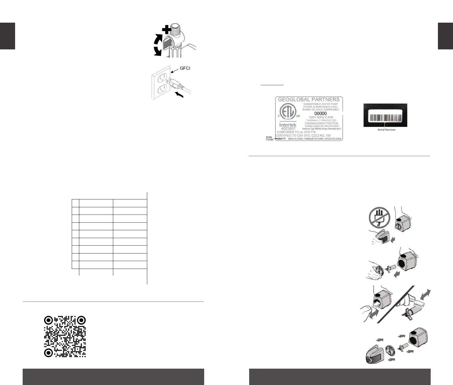
MAINTENANCE & TROUBLESHOOTING
Always disconnect units from the power source before
beginning any maintenance or work on the unit.
Step 1. Remove the inlet screen.
Step 2. Remove the impeller cover
to expose the impeller assembly.
Remove the impeller assembly
by gently pulling on the impeller
blades. The impeller is held in place
by a manget
Step 3. Use a soft cloth or brush
and warm water to clean the
impeller, the inside of the impeller
housing and the rotor housing.
Step 4. Reassemble all pump
parts and place in water before
reconnecting to the power source.