Do you have a question about the TOWA AX-100 and is the answer not in the manual?
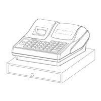
Details the cash register's front display, rear display, printer model, ports, power supply, keyboard features, drawer compatibility, and software language support.
Outlines the machine's capabilities including settings, department numbers, PLU limits, tax rates, clerk functions, reports, payment types, and other operational features.
Explains the control lock's modes (Program, Lock, Register, Read, Reset) and how to switch between them using manager or operator keys.
Provides step-by-step instructions for clearing the cash register's memory, settings, and sales information to a factory default state.
Details the procedure to recover from system loops or errors by resetting the cash register, preserving program and sales data.
Describes the cash register's power input, transformer output, and how +VCC, +VHH, and +5V voltages are generated and supplied to components.
Details the circuit responsible for generating CPU reset signals upon power-on or power failure, including timing considerations.
Explains the circuitry for the 8-digit, 8-segment LED front display and the line-row scanning keyboard input mechanism.
Describes the voltage supply for the rear display's LEDs, including selection and segment signals.
Details the thermal printer's drive voltage sources (+VHH for motor, +5V for head) and CPU control.
Explains the RJ45 port and the MAX202SE IC used for TTL/COMS to RS232 level conversion for COM communication.
Lists the CPU pin assignments, I/O functions, and descriptions, mapping pins to various peripheral controls and interfaces.
Details the HM628512BLTT Series RAM chip, including its pin functions for address inputs, data I/O, chip select, and enable signals.
Provides a flowchart for diagnosing and resolving issues where the entire machine does not respond, covering power, fuse, and component checks.
Offers a troubleshooting guide for data-related malfunctions, including checks for time display, report data, and battery voltage.
| Brand | TOWA |
|---|---|
| Model | AX-100 |
| Category | Cash Register |
| Language | English |