SERVO
Because there are a variety of specific applications for servos in R/C modeling, different servos are designed for differ-
ent applications.Tower Hobbies offers a large line-up of servos which you can choose from (see page 8). Mount all ser-
vos into the model as shown in your model’s manual. Use the rubber grommets, screws and brass eyelets supplied
when mounting your servos (see figure 4). Do NOT over-tighten the mounting screws. The servos should be able to
move slightly to compensate for engine vibration. For each servo, use a servo horn long enough to accommodate the
entire range of movement for that particular control.
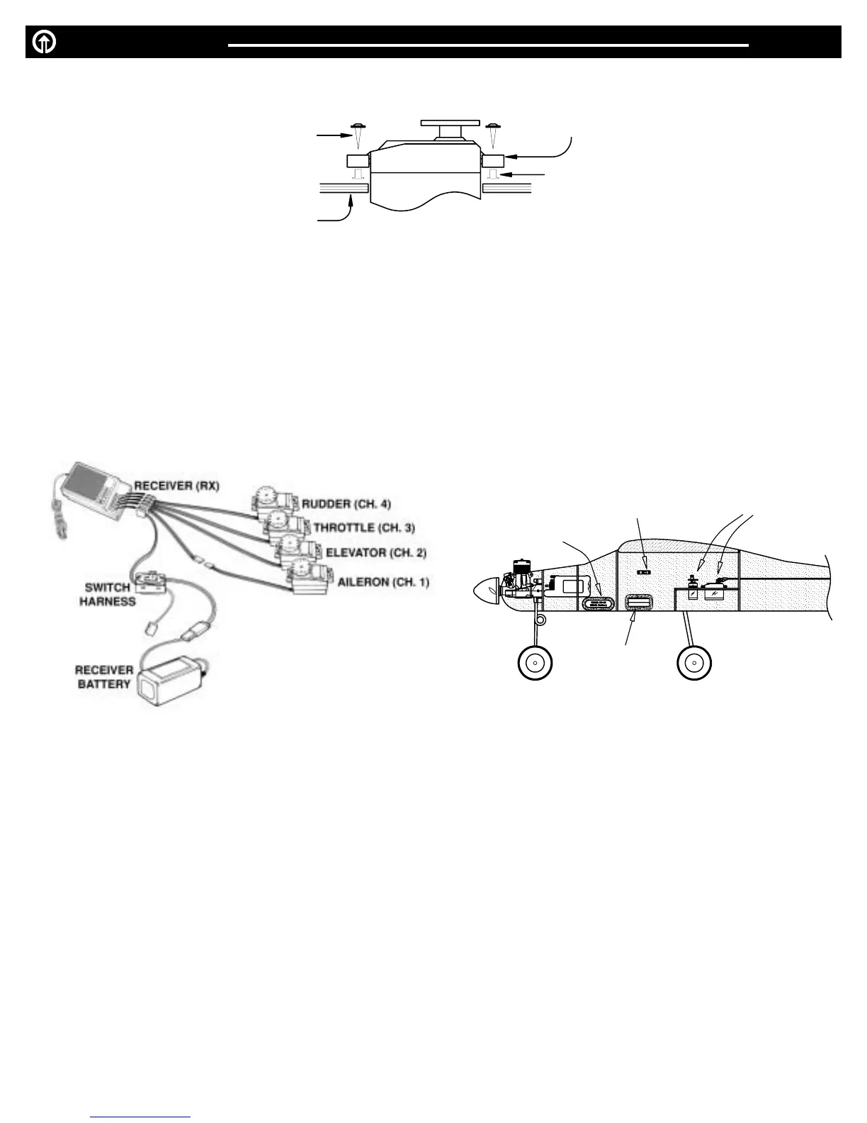
RECEIVER, SWITCH HARNESS AND RECEIVER BATTERY
After the receiver and servos are mounted in your model, connect the servos and switch harness to the receiver as
shown in figure 5. Turn on the Tx, then the Rx switch harness. Make sure all servos operate according to the movement
of the Tx sticks. Center all trim levers, turn off the Rx switch harness, then the transmitter, and be careful not to move the
servo arms from their centered position during installation.
The servo connectors are keyed to prevent improper con-
nection, but do pay close attention when connecting them to the receiver. The black wire goes toward the outside edge
of the receiver case.
Mount the switch harness to the side of the fuselage away from the engine exhaust (refer to your model’s instruction man-
ual). Connect the red plug to the receptacle on the Rx marked “B” for battery. Connect the 4.8V Rx battery to the female
plug on the switch harness. Wrap the receiver and battery in
1
¼
4
"
-
1
¼
2
"
foam rubber (HCAQ1000, HCAQ1050) to reduce vibra-
tion.
Route the receiver antenna according to the model’s instructions. Do NOT cut or coil the antenna or you may lose
adequate operational range.
Mount the receiver and battery in the model as shown in figure 6. NOTE: You may mount the
battery fore or aft of the location shown to better balance the aircraft.
Range test the radio system prior to flight.With the Tx antenna collapsed, you should be able to smoothly control move-
ment of all control surfaces on your model from at least 100 ft. on the ground. If not, refer to the 4FM’s Troubleshooting
Guide on page 7 before proceeding.
INSTALLATION PAGE 4
MOUNTING
SURFACE
SCREW
GROMMET
BRASS
EYELET
SERVO
FIGURE 4
FIGURE 5
FIGURE 6
RX BATTERY
SWITCH
HARNESS
SERVOS
RECEIVER
 Loading...