❍ 3. Test fit the Dorsal Fin into position in front of the Fin as shown.
The Dorsal Fin should fit flush against both the Fuselage Top and Fin.
Sand as necessary to provide for a good fit of the Dorsal Fin. Use a
straightedge to make sure the Dorsal Fin is aligned with the Fin. Glue
it to the Aft Fuselage Top and Fin as shown using Medium CA.
❍ 4. Apply Medium CA to any remaining Fin, Stab and Fuselage joints
that are not thoroughly glued. Be sure to flip the fuselage over and
check the joints on the bottom side in addition to those on the top.
❍ 5. Sand the joints at the back of the fuselage smooth. For a nice
touch, slightly round all the corners of the fuse.
MOUNT THE ENGINE
❍ 1. Temporarily bolt the engine mount to the firewall using four
6-32 x 1" screws with #6 flat washers. Don't tighten the screws
completely until after the engine has been positioned.
Note: You will need your engine for the following steps. From
here on it is a good idea to plug the holes in your engine so balsa
dust cannot get in. Stuff a piece of paper towel into the exhaust
and carburetor to seal them off.
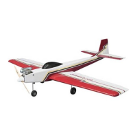
❍ 2. Remove the needle valve from your engine. Position the
engine on the engine mount and adjust the engine mount halves
until the engine mounting lugs will sit flat on the rails. Position
the mount so the firewall centerline is centered between the
"tick" marks on the mount. Tighten the screws to hold the mount
firmly in position against the firewall.
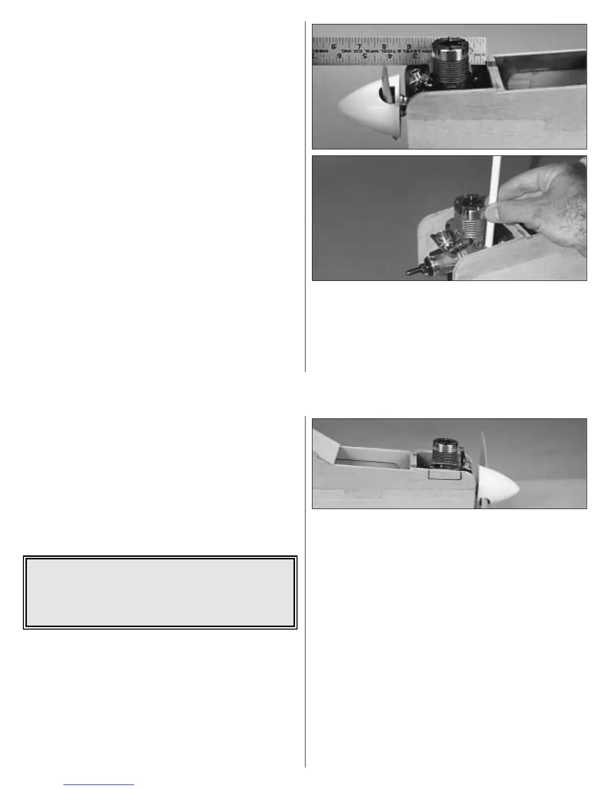
❍ 3. Mount the spinner backplate on the crankshaft of your
engine. Position the engine so that the spinner backplate is 3-3/4"
from the firewall. Carefully mark the engine mounting holes on
the rails with a sharpened piece of wire or a pencil.
NOTE: If installing a 4-stroke engine, the engine may be forward
of the recommended position to allow for the choke mechanism.
This is acceptable and will not cause a balance problem.
35
❍ 4. Remove the engine and engine mount from the fuse. Use a
center punch or sharpened nail to "dimple" the marks on the rails,
then drill a 3/32" hole through the rails at each punch mark. If
you have access to a drill press, this is the best tool for the job.
However, if you are using a hand-held electric drill, try to keep
the bit perpendicular to the rails.
❍ 5. Install a threaded ball stud in the bottom hole of the
carburetor arm of your engine and secure it with a 0-80 nut and
a drop of epoxy or thread locking compound. Fasten the engine
to the mount with four #4 x 5/8" screws. Hint: Add a drop of
household oil to the #4 sheet metal screws to make them a little
easier to screw into the mount.
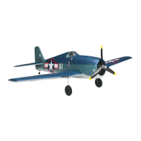
❍ 6. Carefully and neatly cut away some of the fuselage side so
you can reach the needle valve if necessary. A Dremel
®
tool with
a sanding drum works well for this.
❍ 7. Use the same procedure to remove some of the fuselage
side to clear the muffler. There should be approximately 1/8"
clearance between the muffler and the fuselage.
NOTE: The THROTTLE PUSHROD location will vary, depending
on the engine used. Plan your installation carefully!
❍ 8.With the engine attached to the mount, plan the throttle
pushrod routing. The pushrod should be located as close as
possible to the fuse side (to allow room for the fuel tank) and the
guide tube should not have any tight bends. Drill a 3/16" hole in
F-1 for the throttle pushrod guide tube.
❍ 9. Cut a piece of tubing to be used for the throttle pushrod
guide tube. It should extend 1/2" past the firewall and 1/2" aft of
F-2. Temporarily install the throttle guide tube through the holes
in the firewall and F-2.
★★★★ Pro Tip: Some modelers prefer to secure the engine
to the mount with machine screws (not supplied) because
they are easier to screw in. The screws recommended for this
are 4-40 x 3/4". Use a #48 drill bit (3/32") to drill the holes,
then tap the threads with a 4-40 tap.
36