Do you have a question about the Toyota 7BNCU15 and is the answer not in the manual?
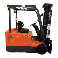
This document is a service manual for the Toyota Stand-Up End-Control Lift Truck, specifically covering models 7BNCU15, 7BNCU18, 7BNCU20, and 7BNCU25, with serial numbers 50,001 and up. It was issued on June 1, 2004, and is identified by the publication number 00700-CL1SM-3. The manual serves as a comprehensive guide for the maintenance, troubleshooting, and repair of these industrial equipment models.
The manual is structured to provide users with a clear understanding of the lift truck's operation and service requirements. It begins with an introductory section on "How to Use This Manual," which likely outlines the organization of the document, explains its design principles, and defines abbreviations and symbols used throughout. This foundational information is crucial for technicians to navigate the manual effectively and interpret its contents accurately.
A significant portion of the manual is dedicated to "Safety," emphasizing the importance of safe practices during operation and maintenance. This section typically includes "Definitions" of safety-related terms, "General Safety" guidelines applicable to all aspects of the lift truck, and specific safety considerations such as "Battery Safety," "Static Precautions," "Jacking Safety," "Towing," and "Welding Safety." These detailed safety instructions are paramount for preventing accidents, protecting personnel, and ensuring the longevity of the equipment. Adherence to these guidelines is not just recommended but often mandatory for compliance with industrial safety standards.
The "Systems Overview" section provides a high-level understanding of the lift truck's various components and their interrelationships. This includes "Lift Truck Dimensions and Specifications," offering an overview of the physical characteristics and performance capabilities of the models. "General System Data" likely delves into the operational parameters and technical details of the truck's core systems. The "Configure Mode" and "Maintenance Mode" sections are particularly important for technicians, as they describe how to access and utilize specific diagnostic and adjustment functionalities of the lift truck's control systems. The "Software Configuration/PC Loader Program" indicates that these lift trucks incorporate advanced electronic controls that can be interfaced with a computer for programming, diagnostics, and updates, highlighting the sophisticated nature of the equipment.
"Planned Maintenance" is a critical section for ensuring the reliable and efficient operation of the lift truck over its lifespan. It typically outlines a schedule of routine inspections, adjustments, and replacements. "Maintenance Guidelines" would provide detailed instructions on how to perform these tasks, including recommended tools, procedures, and safety precautions. "Battery Maintenance" is given its own dedicated subsection, underscoring the importance of proper battery care for electric lift trucks, which includes charging procedures, inspection of terminals, electrolyte levels, and overall battery health to maximize performance and extend battery life.
The manual also includes extensive lists of "Service Information Bulletins" (SIBs) and "Hotline Tech Tips" (HTTs) that affect the specified models. These bulletins and tech tips are crucial for staying updated on known issues, recommended fixes, and best practices that have emerged since the manual's initial publication. The SIBs cover a wide range of topics, from option menu changes and error code information to specific component changes (e.g., tie rod, front axle hub, reduction gear), repair manual corrections, and conversions (e.g., voltage conversions). They also address issues like inching while braking, TMPU inspection standards, contactor cover details, gear case changes, and mini lever pressure relief. Furthermore, SIBs provide information on special service tools, accelerator pedal response tuning, low battery voltage performance reduction, pump motor cooling fan additions, maintenance indicator changes, rear axle flange changes, back-tilt lock valve additions, display battery replacement, front axle shaft changes, and drive motor rotor sensor modifications.
Similarly, the HTTs provide practical advice and solutions for common problems encountered in the field. These tips cover topics such as controller issues, drive motor overheating, hydraulic oil changes, rear axle flange details, cast iron hydraulic pump information, plate to frame main rollback, steer motor operation after auto shutdown, excessive hydraulic return circuit back pressure, fluid for cold storage, erratic display issues, ROM write procedures, mast shimming variance, counterweight retention and squeaking, and steer system air purging. The HTTs also delve into specific error codes (e.g., A5, CB-2, E2-1, FE-4, 72-4), power steer motor issues, load sensor problems, gradeability, tilt speed, side panels, motor bearing/RPM sensor, E3 display, hour meter, drive tire compounds, differential oil level, seat switch testing, attachment installation, thicker floor mats, CPU card installation, computer board replacement, wrench icon, contactor tip replacement, slow travel, differential gear noises, gear number three failures, F1 fuse issues, drive unit part numbers, drive transistors, hydraulic oil for cold storage, string cutters, OPSS tilt back lock valve, CU322 updates, interface card replacement, gear case oil and sealing, steer cylinder changes, jerky creep speed, new hydraulic oil, optional 12V power supply, DC/MD card troubleshooting, repair manual clarifications, current sensors, and class 1 gear noise.
The inclusion of these bulletins and tech tips makes the service manual a living document, reflecting ongoing improvements and solutions to real-world operational challenges. Technicians are expected to consult these updates to ensure they are using the most current information and procedures for servicing the Toyota Stand-Up End-Control Lift Trucks. The comprehensive nature of this manual, from basic safety to advanced troubleshooting and maintenance updates, underscores its importance as an indispensable resource for anyone involved in the upkeep and repair of these specific Toyota lift truck models.
| Model | 7BNCU15 |
|---|---|
| Manufacturer | Toyota |
| Load Capacity | 3000 lbs |
| Maximum Lift Capacity | 3000 lbs |
| Power Source | Electric |
| Fuel Type | Electric |
| Mast Type | 3-Stage |
| Lift Speed (loaded/unloaded) | 98 ft/min |
| Fork Dimensions | 42 x 4 x 1.5 inches |