Do you have a question about the Toyota C-HR Hybrid 2017 and is the answer not in the manual?
| Brand | Toyota |
|---|---|
| Model | C-HR Hybrid 2017 |
| Category | Automobile |
| Language | English |
Explains how the C-HR Hybrid operates in various driving modes using gasoline and electric power.
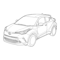
Details external identification features like the HYBRID logo and fuel filler door location.
Describes interior identification features such as the instrument cluster and READY indicator.
Identifies the gasoline engine and high voltage power cables in the engine compartment.
Provides key technical specifications for the C-HR Hybrid, including engine, motor, and battery details.
Details how the vehicle operates, including the READY indicator and power source usage.
Details the HV battery pack, its voltage, module count, and electrolyte composition.
Lists the electric motor, inverter/converter, power cables, A/C compressor, generator, and DC-DC converter.
Information on recycling the HV battery pack, advising contact with a Toyota distributor or dealer.
Describes the 12 Volt auxiliary battery, its function, and location in the engine compartment.
Explains the high voltage fuse, relays, and how they protect against electrical hazards.
Critical warning about residual high voltage and avoiding contact with high voltage components.
Details the function and use of the service plug grip to cut off the high-voltage circuit.
Reiterates the warning about residual high voltage and the dangers of touching high voltage parts.
Lists essential protective clothing, safety goggles, gloves, and electrical testers for dismantling.
Provides PPE and procedures for handling NiMH electrolyte spills, including neutralization with boric acid.
Emphasizes residual high voltage danger and the need to avoid touching high voltage components.
Instructions to shut off the ignition and disconnect the negative terminal of the auxiliary battery.
Procedure to remove the battery service hole cover by releasing clips and claws.
Guide to removing the service plug grip to cut off the high voltage circuit, including waiting time.
Warning about residual high voltage after removing the service plug grip and SRS component safety.
Instructs to use a 'HIGH VOLTAGE WORK IN PROGRESS' sign to alert other technicians.
Procedure to remove the IG2-MAIN fuse if the service plug grip cannot be removed.
Instructions to insulate disconnected high-voltage connectors and terminals with tape.
Procedure to check the HV battery area for electrolyte leakage and neutralize it.
Instructions for washing skin and clothing immediately if electrolyte comes into contact.
Procedure for eye contact with electrolyte, including seeking medical attention.
General guidance to remove other parts following procedures similar to conventional vehicles.
Warnings about insulated gloves, service plug grip, residual power, tester readings, and SRS components.
Instruction to shut off the ignition and ensure the READY indicator is off.
Procedure to loosen the nut and disconnect the cable from the negative auxiliary battery terminal.
Instructions to remove the battery service hole cover by disengaging clips and claws.
Detailed steps for removing the service plug grip, including cautions on risk, waiting time, and pocket storage.
Procedure to disconnect the engine wire by releasing lock levers on inverter connectors.
Instructions to remove the connector cover assembly from the inverter with converter assembly.
Procedure to measure terminal voltage using a voltmeter to confirm 0V.
Instructions to lift and disengage the rear seat cushion assembly from frame and lock hooks.
Procedure to disengage claws to remove the rear seat cushion lock hook.
Instructions to disengage claws to remove the rear door scuff plate LH.
Procedure to remove the rear under side cover LH by releasing clips and claws.
Instructions to remove the rear door scuff plate RH, using the same procedure as LH.
Instructions to remove the rear under side cover RH, using the same procedure as LH.
Procedure to disengage clips and guides to remove the rear under cover.
Instructions to remove the rear seat cushion leg sub-assembly by removing bolts.
Procedure to disconnect the blower assembly connector, clamps, and bolts to remove it.
Instructions to remove the HV battery cover panel RH using the service plug grip and removing bolts/nuts.
Procedure to disconnect HV battery junction block connectors and shield ground, with insulation caution.
Instructions to disengage clamps and disconnect EV battery plug and HV battery junction block connectors.
Procedure to remove the hybrid battery exhaust duct by removing clips and claws.
Instructions to disengage clamps and disconnect the battery voltage sensor connector.
Procedure to remove the HV battery by removing 5 bolts, with cautions on handling and weight.