EasyManua.ls Logo

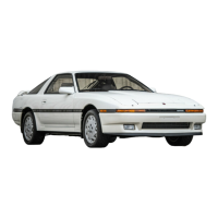
Toyota ST184 Series User Manual

Toyota ST184 Series
213 pages
To Next Page IconTo Next Page
Page #1 background imageLoading...
Page #1 background image
FOREWORD
This wiring diagram has been prepared to provide information
on the electrical system of the 1990 TOYOTA CELICA (FWD).
Applicable models: AT180 Series
ST184 Series
For service specifications and repair procedures of the above
models other than those listed in this manual, refer to the
following manuals:
Manual Name Pub. No.
1990 Celica Repair Manual
1990 Celica New Car Features
RM149U
NCF056U
All information in this manual is based on the latest product
information at the time of publication. However, specifications
and procedures are subject to change without notice.
TOYOTA MOTOR CORPORATION
This vehicle has an SRS AIRBAG (referred to as the airbag in the remainder
of this manual).
When handling airbag components (removal, installation or inspection, etc.),
always follow the directions given in the repair manuals listed above to
prevent the occurrence of accidents and airbag malfunction.
NOTICE
Question and Answer IconNeed help?

Do you have a question about the Toyota ST184 Series and is the answer not in the manual?

Toyota ST184 Series Specifications

General IconGeneral
BrandToyota
ModelST184 Series
CategoryAutomobile
LanguageEnglish

Summary

Foreword

SRS Airbag Handling Notice

Important safety notice regarding SRS Airbag handling and following repair manual directions.

Electrical Troubleshooting Procedures

Voltage and Continuity Checks

Methods for performing voltage checks and continuity/resistance tests on electrical circuits.

Finding a Short Circuit

Procedure for locating short circuits using a test light and connector inspection.

Power Source Current Flow Chart

Starting and Ignition System

Starting System Parts Locations

Identifies the locations of key components within the starting and ignition system.

Engine Control System (5S-FE)

Engine Control Input Signals

Details the various input signals received by the ECU from sensors and switches.

Engine Control System Operation

Explains the control logic and operation of the EFI and ESA systems within the ECU.

Taillight System Wiring

Stop Light System Wiring

Turn Signal and Hazard Warning Light System

Power Window System

Power Window Parts Location

Identifies the locations of key components for the power window system.

Door Lock System

Rear Window Defogger System

ECT System Operation

ECT Gear Shift Operation

Details how the ECU selects gears based on input signals and controls solenoids for shifting.

Shift Lock System

Cruise Control System (Motor Type)

Cruise Control Set Operation

Details the procedure for setting and controlling vehicle speed using the cruise control system.

Cruise Control Manual Cancel Mechanism

Explains how to manually cancel cruise control operation under various conditions.

Cruise Control System (Vacuum Type)

Cruise Control Driving and Cancel Mechanism

Explains cruise control driving, including cancel and control valve operations.

ABS System Operation and Troubleshooting

ABS Input Signals and System Operation

Details sensor inputs and how the ABS ECU controls hydraulic pressure for stability.

ABS Service Hints and ECU Checks

Provides service hints, voltage checks, and resistance values for the ABS ECU.

SRS Airbag System Precautions and Operation

SRS Airbag Safety Precautions

Crucial safety instructions for inspecting and repairing the SRS airbag system.

Airbag Connector Mechanisms

Explains the functions of airbag connector mechanisms: activation prevention and electrical connection check.

Connector Twin-Lock Mechanism

Details the twin-lock mechanism for connectors to ensure reliable connections and prevent accidental unlocks.

SRS Airbag System Components and Locations

Combination Meter System

Radiator Fan and AC System (Automatic, Push Type)

Cooling Fan Operation (Automatic, Push Type)

Explains the operation of cooling fans at low and high speeds under automatic AC control.

Heater Blower Motor Operation (Push Type)

Details blower motor operation at low, high, and medium speeds using push-type controls.

Radiator Fan and AC System (Manual, Dial Type)

Cooling Fan Operation (Manual, Dial Type)

Explains cooling fan operation at low and high speeds for manual dial type blower controls.

Radiator Fan and AC System (Manual Fan, Dial Type)

Cooling Fan Operation (Manual Fan, Dial Type)

Explains cooling fan operation at low and high speeds for manual dial type blower controls.

Heater Blower Motor Operation (Manual, Dial Type)

Details blower motor operation at low, high, and medium speeds using dial type controls.

Related product manuals