Do you have a question about the Toyotomi GAN-A135GVR-T3 and is the answer not in the manual?
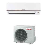
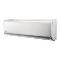
Provides an overview of the air conditioner models and features.
Details technical specifications for indoor and outdoor units.
Illustrates performance curves based on compressor speed.
Shows how cooling/heating capacity changes with outdoor temperature.
Presents performance data under rated conditions.
Displays noise levels at different fan speeds and frequencies.
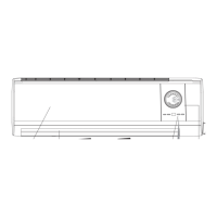
Provides dimensional drawings and data for the indoor unit.
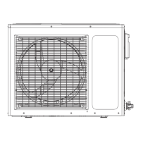
Provides dimensional drawings and data for the outdoor unit.
Shows the electrical connections and wiring layout.
Explains the buttons and functions of the remote controller.
Details the operation of various modes and unit functions.
Covers compensation and calibration for input parameters.
Describes the fundamental operating conditions and processes.
Illustrates required clearances for unit installation.
Outlines the step-by-step process for installing the unit.
Lists and describes the components to check before installation.
Provides guidelines for choosing optimal installation sites.
Specifies safety and connection requirements for power supply.
Details the steps for safely installing the indoor unit.
Details the steps for safely installing the outdoor unit.
Explains procedures for vacuuming and checking for refrigerant leaks.
Outlines checks and tests to perform after installation.
Highlights safety measures before performing maintenance or repair.
Guides on interpreting LED indicators for fault diagnosis.
Provides systematic steps for diagnosing and resolving unit faults.
Provides conversion tables for temperature units.
Details pipe specifications, length, and refrigerant charging.
Lists resistance values for ambient temperature sensors.
| Model | GAN-A135GVR-T3 |
|---|---|
| Brand | Toyotomi |
| Category | Air Conditioner |
| Type | Split System |
| Refrigerant | R32 |
| Power Supply | 220-240V, 50Hz |
| EER (Energy Efficiency Ratio) | 3.21 |
| Air Flow (High) | 550 m³/h |