Do you have a question about the Toyotomi GAN GAG A220IV and is the answer not in the manual?
| Brand | Toyotomi |
|---|---|
| Model | GAN GAG A220IV |
| Category | Air Conditioner |
| Language | English |
Diagram identifying major parts of the indoor unit, including panels, louvers, and sensors.
Detailed dimensions and required installation clearances for the indoor unit.
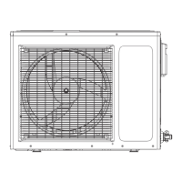
Overall dimensions and required installation clearances for the 18K outdoor unit.
Overall dimensions and required installation clearances for the 24K outdoor unit.
Electrical wiring diagrams for GAN GAG A180IV and GAN GAG A220IV models.
Description of Cooling, Dehumidifying, Fan, Heat, and Auto modes controlled by the remote.
Functions for turning the unit on/off, selecting modes, and setting temperature.
Details on setting timers, sleep mode, fan speed, and swing control.
Details on outdoor unit operating modes and logic for fan control.
Explanation of compressor overload, delay, and other protection functions.
Covers communication, module, demagnetization, overheat protections, and indicator meanings.
Methods for detecting malfunctions in temperature sensors and IPM overheat.
Definitions for the blink patterns of outdoor unit indicators for troubleshooting.
Steps to disassemble the front panel, filter, and air guide louver.
Procedures for removing the front case and the electric box cover.
Steps to disassemble and remove the water tray sub-assembly.
Steps to remove the electric box and the evaporator assembly.
Procedures for removing the motor and the cross flow fan.
Steps to remove the top cover and handle of the outdoor unit.
Procedures for disassembling the rear side plate and rear grill.
Steps for removing the front case and cabinet of the outdoor unit.
Procedures for disassembling the electric box assembly.
Steps to remove the gas/liquid valves and the axial flow fan.
Procedures for removing the outdoor unit motor.
Steps to disassemble the 4-way valve and the capillary sub-assembly.
Detailed steps for removing the compressor from the outdoor unit.
Visual representation of the indoor unit with numbered components for identification.
List of indoor unit components for GAN A180IV with part codes and quantities.
List of indoor unit components for GAN A220IV with part codes and quantities.
Visual representation of the outdoor unit with numbered components for identification.
List of outdoor unit components for GAN A180IV with part codes and quantities.
List of outdoor unit components for GAN A220IV with part codes and quantities.
Diagnosing and resolving issues related to air circulation and refrigerant flow problems.
Addressing problems caused by improper installation or environmental conditions.
Troubleshooting faults where the fan or compressor fails to operate correctly.
Diagnosing and fixing common issues like water leakage and abnormal sounds or shaking.
Analysis and processing steps for compressor, system, and PTC protection malfunctions.
Methods for analyzing and processing communication, sensor, and IPM module malfunctions.
Step-by-step guide for handling module protection issues.