Do you have a question about the TPS Blue M DC 146 Series and is the answer not in the manual?
Provides contact details and company background for support and service inquiries.
Outlines critical safety warnings, symbols, and precautions for operating the equipment.
Details the oven's applications, models, workspace capacities, and temperature ratings.
Explains the heating, cooling, and airflow mechanisms employed by the oven.
Describes key components, controllers, and optional features integrated into the oven.
Specifies the environmental conditions and requirements for safe and optimal oven operation.
Lists provided drawings, information, and vendor manuals for system components.
Instructions for inspecting and safely uncrating the oven upon delivery.
Guidelines for selecting an appropriate location and performing the initial installation.
Details the equipment access and features specific to the DC and DCW oven models.
Details the equipment access and features specific to the DCI oven model.
Details the equipment access and features specific to the DCC oven model.
Instructions for connecting the exhaust port for Model DC and DCW ovens.
Procedures for connecting the water supply for the optional cooling coil.
Guide for connecting the inert gas supply to the Model DCI oven.
Guide for connecting the inert gas supply to the Model DCC oven.
Explains the chamber venting mechanisms for Models DCI and DCC.
Instructions for connecting compressed air for the optional pneumatic door lock.
Crucial information on power requirements, voltage, and connection procedures.
Steps for safely applying power to the oven after installation.
Provides a general overview of the oven's high volume horizontal airflow system.
Explains the airflow path within the oven's workspace for conditioning.
Details how to adjust air intake and exhaust dampers for different airflow systems.
Describes the airflow characteristics specific to the DCI and DCC models, including inert gas.
Explains the HEPA/ULPA filtration system used in Model DCC for clean room specifications.
Details the inert gas system, purge cycles, and flow rates for the Model DCI.
Describes the inert gas system for the Model DCC, focusing on gas flow adjustment.
Introduces the optional oxygen analyzers/transmitters for monitoring chamber atmosphere.
Explains how the oxygen analyzers/transmitters sample process air and determine oxygen concentration.
Lists specifications for percent oxygen analyzers and transmitters.
Lists specifications for trace oxygen analyzers and transmitters.
Highlights the functional differences between analyzers and transmitters.
Describes controlling inert gas injection rates using oxygen monitoring.
Explains the oven's electric heating elements and the heat control circuitry.
Details how to cool the oven using ambient air by adjusting dampers.
Describes the optional water-cooled coil for enhanced cooling performance.
Explains how both non-profiling and profiling controllers manage oven temperature.
Covers the standard non-profiling controllers like Blue M Stat-350 and Yokogawa UT350.
Details optional profiling controllers such as Blue M PRO series and Watlow F4.
Explains the function and operation of the Overtemperature Protection (OTP) controller.
Describes the optional Eagle Signal digital process timer for timing cycles.
Details the optional Grasslin Digi 20E 24-hour/7-day digital timer for scheduling operations.
Details the optional Grasslin FM1D 24-hour/7-day digital timer for scheduling operations.
Explains the function of the optional door limit switch for process cycle control.
Describes the optional electro-mechanical door lock for preventing unauthorized opening.
Details the optional pneumatic door lock system for securing the oven door.
Explains the optional light tower indicators and their meaning during operation.
Describes the optional chart recorder for logging temperature and other parameters.
Provides a step-by-step guide for operating the oven, including controller types.
Lists specific maintenance tasks and inspection periods for oven components.
A schedule and log for tracking preventative maintenance activities.
| Brand | TPS |
|---|---|
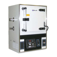
| Model | Blue M DC 146 Series |
| Category | Industrial Equipment |
| Language | English |