©2000 Trace Engineering
2.0 INSTALLATION
5
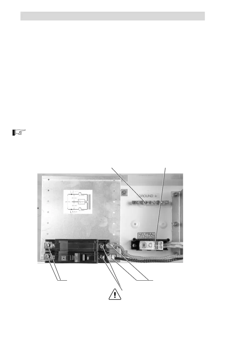
Connection Points
The connection points for input/output wiring is as follows:
All 240 volt AC (input or output) wires connect to the left-hand side of the
breaker, points A and C (Figures 6 and 7).
All 120 volt AC wires connect to the service crimps located on the breaker,
points B and D (Figures 6 and 7).
All neutral wires connect to the NEUTRAL block in the T240.
All ground wires connect to the GROUND block in the T240.
The ganged circuit breaker used in the T240 opens both circuit breakers if
either one receives a current draw in excess of its rating (i.e., 25 amps).
Any exceptions are noted in the procedure.
NOTE: Due to continued product improvement, parts availability, etc.,
photographs used in this manual may vary slightly from actual current
production models.
Figure 5
Step-up Configuration Connections
240 Volt AC
Input/Output
120 Volt AC Input/Output
service crimps
GROUND block NEUTRAL block
Factory Wiring DO NOT
REMOVE OR ADD WIRES
TO THESE TERMINALS!
 Loading...