©2000 Trace Engineering
2.0 INSTALLATION
8
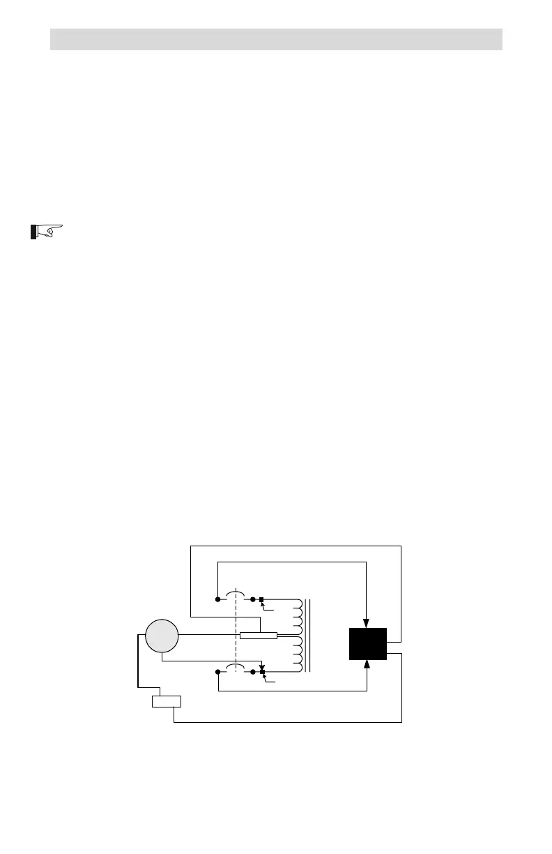
Step-up Configuration
This configuration allows for a 240 volt AC load to be supplied from a
120 volt AC input source. The voltage output of the autotransformer doubles
(from 120 to 240 volts AC) and the total output current available is one half.
Procedure
The wire terminals accept wire sizes from #14 AWG to #2 AWG. Use the
proper size wire for the load connected.
120 Volt AC Input (source)
NOTE: Refer to the previous instructions on connecting wires to the service
crimp.
Connect the 120 volt AC HOT wire (from an inverter, generator or
utility) to service crimp (point B) of the breaker as shown in Figure 8.
Connect the neutral wire (from an inverter, generator or utility) to the
NEUTRAL block in the autotransformer.
Connect the ground wire (from an inverter, generator or utility) to the
GROUND block in the autotransformer.
240 Volt AC Outputs (load)
Connect a black wire from the L1 connection on the breaker (point A),
to the loads L1 connection.
Connect a red wire from the L2 connection on the breaker (point C),
to the loads L2 connection.
Connect a white wire from the NEUTRAL block in the autotransformer
to the loads neutral connection.
Connect a green wire from the GROUND block in the autotransformer
to the loads ground connection.
Figure 8
Step-up Configuration Schematic
NEUTRAL
L2
L1
975-S00-003
120 VAC
Source
Ground
240 VAC
Load
L2
OUT
L1
OUT
N
G
Service
Crimp
Service Crimp
HOT
A
B
N
G
N
G
D
C
N
G
 Loading...