©2000 Trace Engineering
2.0 INSTALLATION
9
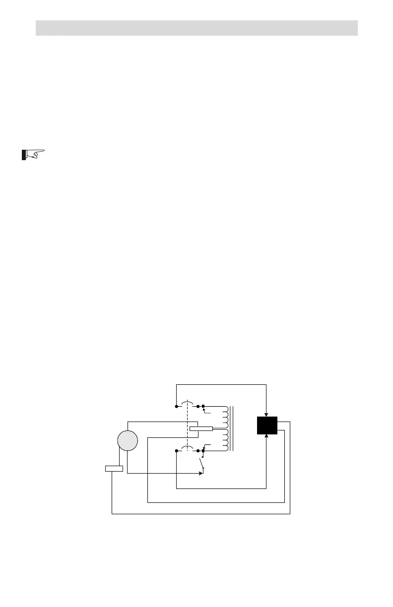
Figure 9
Control Switch Wiring for Deep Well Pump
Deep Well Pump Wiring
This wiring configuration allows the control switch for the pump to be
connected between the 120 volt AC source and the HOT input of the T240. In
this arrangement, there is no transformer idle power consumption when the
switch is open and the pump is not running. The control switch can be either a
float, pressure or manual type.
Procedure
120 Volt AC Inputs (source)
NOTE: Refer to the previous instructions for connecting wires to the service
crimp on page 4 and Figure 4.
Connect the pumps control or pressure switch to the service crimp
(point B) on the lower breaker.
Connect the 120 volt AC HOT wire (from an inverter, generator, or
utility) to the free end of the control switch.
Connect the neutral wire (from an inverter, generator or utility) to the
NEUTRAL block in the autotransformer.
Connect the ground wire (from an inverter, generator or utility) to the
GROUND block in the autotransformer.
240 Volt AC Outputs (load)
Connect a black wire from the L1 connection on the breaker (point A),
to the pumps L1 connection.
Connect a red wire from the L2 connection on the breaker (point C),
to the pumps L2 connection.
Connect a white wire from the NEUTRAL block in the autotransformer
to the pumps neutral connection.
Connect a green wire from the GROUND block in the autotransformer
to the pumps ground connection.
NEUTRAL
L2
L1
975-S00-005
120 VAC
Source
240 VAC
Deep
Well
Pump
L2
OUT
L1
OUT
N
G
Service
Crimp
Service
Crimp
Ground
Control Switch
D
B
A
N
N
G
G
C
L1
L2
N
HOT
 Loading...