©2000 Trace Engineering
2.0 INSTALLATION
10
240 Volt AC Source120 Volt AC to Loads (Step-down Configuration)
This configuration allows a 120 volt AC load to be supplied from a
120/240 volt AC input source such as a utility grid. The voltage output of the
autotransformer halves (from 240 to 120 volts AC) and the total output current
available for the 120 volt AC output doubles. This arrangement is useful for
splitting the current of a battery charger between each leg of the 240 volt AC
source, reducing losses in the wiring. This is especially important in long cable
runs or when charging from a 120/240 volt AC output generator.
240 Volt AC Input (source)
Connect the L1 AC HOT wire (from the utility grid) to point A on the
lower breaker as shown in Figure 10.
Connect the L2 AC HOT wire (from the utility grid) to point C on the
upper breaker as shown in Figure 10.
Connect the neutral wire (from the utility grid) to the NEUTRAL block
in the autotransformer.
Connect the ground wire (from the utility) to the GROUND block in the
autotransformer.
120 Volt AC Output (load)
Connect a black wire from the service crimp (point B), to the loads
HOT connection.
NOTE: Refer to the previous instructions located on page 4 and Figure 4 for
connecting wires to the service crimp.
Connect a white wire from the NEUTRAL block in the autotransformer
to the loads neutral connection.
Connect a green wire from the GROUND block in the autotransformer
to the loads ground connection.
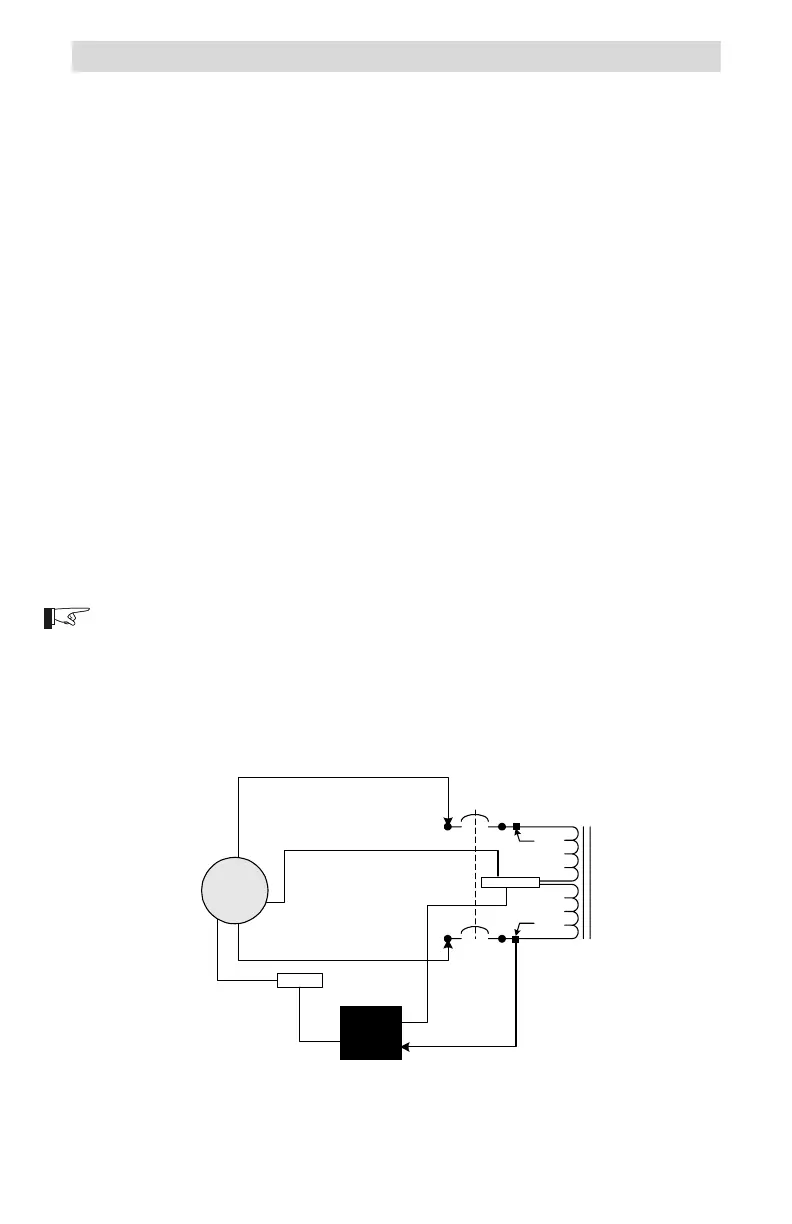
Figure 10
Step-down Configuration Schematic
NEUTRAL
L2
L1
975-S00-006
120 VAC
LOAD
(inverter/
charger)
L2
L1
N*
Service
Crimp
Service
Crimp
Ground
G
N
120 VAC HOT
OUTPUT TO LOAD
G
120/240 VAC
Source
(grid)
D
B
N*
N
A
G
G
C
*NOTE: For 240 VAC only source
installations, the neutral wire is not
required.
 Loading...