©2000 Trace Engineering
2.0 INSTALLATION
11
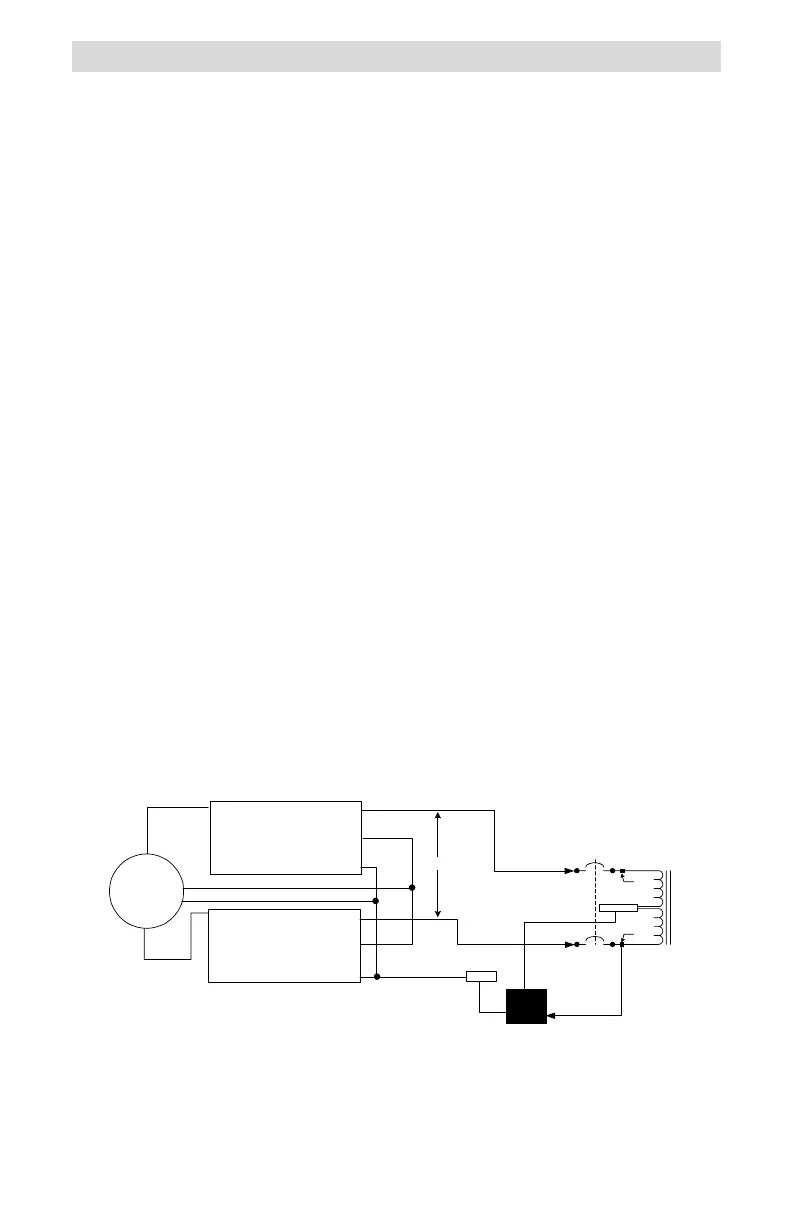
Figure 11
Step-down Configuration Schematic (Dual Inverters)
Step-down Connection of Stacked-pair Inverters
The T240 can also be used to step down the voltage from a stacked pair of
DR or SW Series inverters. In this configuration, the neutral of the inverters
must be isolated from the neutral block of the T240 Autotransformer, or the
inverters may over-current trip when they synchronize to an AC generator. This
configuration may not be in compliance with the NEC. Consult your local and
national electrical codes for requirements. This configuration provides double
the output current at 120 volts AC.
Procedure
Inverter Inputs to T240
Connect the HOT output of Inverter #1 to point A on the lower
breaker.
Connect the HOT output of Inverter #2 to point C on the upper
breaker.
Connect the ground wire from the inverters to the GROUND block in
the T240.
T240 Output to 120 Volt AC Load
Connect the ground wire from the load to the GROUND block in the
T240.
Connect the neutral wire from the load to the NEUTRAL block in the
T240.
Connect the HOT wire (120 volt AC) from the load to the service
crimp on lower breaker (point B).
Connect the inverters as specified in the inverters operation manual
for stacked (120/240 volt AC) operation.
NEUTRAL
L2
L1
975-S00-007A
120 VAC
LOAD
(high
current)
HOT
N
Service
Crimp
Service
Crimp
G
N
120 VAC HOT
OUTPUT TO LOAD
G
HOT
Out
Neutral
Ground
I
nverter #2
120 V ac Output
HOT
Out
Neutral
Ground
I
nverter #1
120 V ac Output
Ground
240 VAC
L2
L1
G
N
HOT
240 VAC
Generator
HOT
In
HOT
In
N
G
L1
L2
D
C
N
B
A
G
G
 Loading...