Do you have a question about the Trane 4TTX5030A1000A and is the answer not in the manual?
| Model Number | 4TTX5030A1000A |
|---|---|
| Category | Air Conditioner |
| Type | Split System |
| SEER Rating | 16 |
| HSPF Rating | Not Applicable |
| Refrigerant | R-410A |
| Voltage | 208/230V |
| Phase | 1 |
| Frequency | 60 Hz |
| Cooling Capacity | 30000 BTU |
| Compressor Type | Scroll |
| Indoor Unit Compatibility | Trane Air Handlers and Coils |
Important safety precautions for installation, operation, and service.
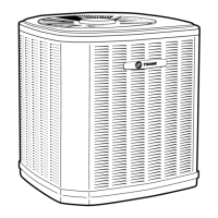
Provides dimensions and estimated weights for different condensing unit models.
Details maximum refrigerant line length and vertical change limits.
Guidelines for optimal outdoor unit placement to ensure airflow and minimize noise.
Recommendations for units installed near salt water environments.
Steps for unpacking and preparing the unit for installation.
Guidelines for selecting and installing a proper support pad for the unit.
Specifies line and valve connection sizes for various unit models.
Information on factory refrigerant charge and when adjustments are needed.
Emphasizes insulation for the vapor line and preventing metal-to-metal contact.
Precautions for using existing refrigerant lines in retrofit applications.
Guidelines for routing refrigerant lines to prevent noise and ensure proper installation.
Step-by-step instructions for preparing and brazing refrigerant lines.
Continues brazing instructions, including nitrogen purge and heat damage prevention.
Procedure for leak checking refrigerant lines using nitrogen and soapy solution.
Steps for evacuating the system to achieve a deep vacuum using a micron gauge.
Instructions for opening the gas service valve, ensuring prior completion of leak check and evacuation.
Cautions and steps for opening the liquid line service valve safely.
Table detailing maximum wire lengths for low voltage wiring based on gauge.
Wiring diagram for connecting an air handler to the outdoor unit.
Wiring diagram for connecting a variable speed furnace to the outdoor unit.
Wiring diagram for communicating systems with 24V control.
Wiring diagram for communicating systems in comm. mode.
Wiring diagram for AM7 air handler connections.
Wiring diagram for GAM5 air handler connections, including notes on wiring.
Safety warnings and requirements for high voltage power supply connections.
Requirement to install a separate disconnect switch for high voltage.
Instructions for grounding the outdoor unit according to codes.
Step-by-step procedure for starting up the installed system.
Guidance on measuring outdoor and indoor temperatures for charging.
Instructions to measure line length and lift for subcooling calculations.
Charts used to determine subcooling corrections based on line length and lift.
Requirement to stabilize the system before making charge adjustments.
Steps to measure liquid line temperature and pressure at the service valve.
Using measured values and a chart to find the correct liquid gage pressure.
Procedure for adding or recovering refrigerant to match chart values.
Steps to stabilize the system after adjusting refrigerant levels.
Guidance to refer to Service Facts for verifying system performance.
Instructions to record system pressures and temperatures after charging.
Final inspection and checklist for ensuring proper system operation.
A chart listing system faults and their primary/secondary causes.