Do you have a question about the Trane 4TTX8 and is the answer not in the manual?
This document serves as an installer's guide for Trane Condensing Units, specifically the 4TTX8 series. It provides comprehensive instructions for the proper installation, setup, and maintenance of these outdoor units, ensuring optimal performance and reliability. The guide emphasizes adherence to national, state, and local codes throughout all installation phases.
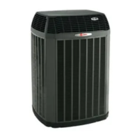
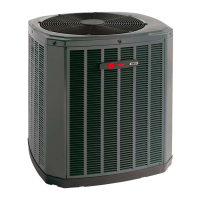
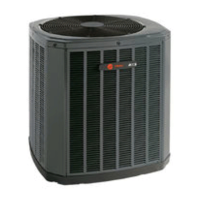
The Trane 4TTX8 Condensing Units are integral components of a central air conditioning system, designed to work in conjunction with an indoor evaporative coil and refrigerant lines to provide cooling for residential and commercial applications. These units are factory-charged with R-410A refrigerant, a high-pressure refrigerant that requires specific handling procedures and approved service equipment. The primary function of the condensing unit is to compress and condense the refrigerant, releasing heat to the outdoor environment, thereby facilitating the cooling cycle within the building.
The installation process for these condensing units is broken down into several key sections, each addressing a critical aspect of setup and operation.
Unit Location Considerations: This section guides installers in selecting an appropriate location for the outdoor unit. It outlines important factors such as ensuring the roof can support the unit's weight if mounted on a roof, recommending proper isolation to mitigate sound and vibration transmission, and specifying minimum clearance requirements for top discharge, access panels, and surrounding shrubbery to ensure adequate airflow and serviceability. The guide also advises against installing the unit near windows or sleeping quarters to prevent noise disturbance and suggests avoiding locations where condensation and freezing defrost vapor might annoy occupants. For cold climates, specific precautions are detailed, including elevating the unit 3-12 inches above the pad or rooftop to allow for snow and ice drainage during defrost cycles, and installing snow drift barriers if necessary.
Unit Preparation: Before installation, the guide instructs installers to inspect the unit for any shipping damage and report it promptly. It also provides instructions on how to safely remove the unit from its pallet by cutting the securing tabs.
Setting the Unit: This section focuses on pad installation, recommending that the support pad (e.g., a concrete slab) be at least 1 inch larger than the unit on all sides, separate from any building structure, level, and high enough above grade to allow for proper drainage. The pad's location must also comply with all relevant codes.
Refrigerant Line Considerations: This is a crucial section that details the requirements for refrigerant piping. It specifies maximum total line lengths (150 feet, including lift) and vertical change limits (50 feet). A table provides standard and alternate line sizes, as well as service valve connection sizes for different models. The guide strongly recommends insulating the vapor line and preventing direct metal-to-metal contact between the liquid and vapor lines. For retrofit applications, installers are cautioned to ensure existing refrigerant lines are the correct size, free of leaks, acid, and oil, and that all joints are brazed, not soldered.
Refrigerant Line Routing: This section emphasizes precautions to prevent noise and vibration transmission from the refrigerant lines into the building structure. It advises using isolation hangers when fastening lines to joists, rafters, or other framing, insulating and isolating lines that run through walls or sills, and isolating lines from all ductwork. Minimizing 90-degree turns is also recommended for efficient routing.
Refrigerant Line Brazing: Detailed steps are provided for brazing the refrigerant lines. This includes deburring and cleaning pipe ends, removing pressure tap caps and valve cores from service valves, purging lines with dry nitrogen, and wrapping wet rags around valve bodies to prevent heat damage during brazing. For units with field-installed external driers, installers must confirm the correct directional flow of the drier. The guide also includes a critical note on avoiding heat damage to the basepan during brazing.
Refrigerant Line Leak Check: After brazing, a leak check is mandatory. Installers are instructed to pressurize the refrigerant lines and evaporator coil to 150 PSIG with dry nitrogen and then check for leaks using a soapy solution at all brazed locations. Any leaks must be repaired before proceeding.
Evacuation: This section outlines the evacuation process to remove non-condensable gases and moisture from the system. It requires evacuating until a micron gauge reads no higher than 350 microns and then verifying that the micron gauge does not rise above 500 microns in one minute after closing off the vacuum pump.
Service Valves: Instructions are provided for opening both the gas and liquid service valves. This includes removing valve stem caps, turning valve stems counterclockwise to the fully open position (1/4 turn for gas, approximately five turns for liquid), and replacing caps, tightening them finger-tight plus an additional 1/6 turn to prevent leaks. Extreme caution is advised when opening the liquid line service valve due to the abrupt release of system charge if not done correctly.
Electrical - Low Voltage and High Voltage: This section covers electrical connections. For low voltage, a table specifies maximum wire lengths for different AWG sizes. Hook-up diagrams are provided for various thermostat and indoor unit configurations (e.g., with TEM 6, TAM 7, and Variable Speed S-Series Furnace). For high voltage, a warning about live electrical components emphasizes safety precautions. Installers must ensure the power supply matches the equipment nameplate, comply with all codes, and follow the unit's wiring diagram. A separate disconnect switch is required at the outdoor unit, and flexible electrical conduit is recommended for high voltage connections to minimize vibration transmission. Grounding the outdoor unit per code requirements is also specified.
Start Up: The start-up procedure includes setting the system thermostat to OFF, turning on disconnects to apply power, and waiting one hour before starting the unit if a compressor crankcase heater accessory is used and the outdoor ambient temperature is below 70°F. Finally, the thermostat is set to ON.
System Charge Adjustment: This critical section details how to verify and adjust the refrigerant charge.
Checkout Procedures and Troubleshooting: The final phase involves operational and checkout procedures to ensure proper performance. A checklist guides installers through verifying leak checks, insulation, refrigerant line security, sealed masonry passages, tight electrical connections, outdoor fan operation, free-draining indoor coil drain line, open registers and grilles, installed return air filter, correct airflow setting, and overall system operation in all modes. A comprehensive troubleshooting table is provided, listing common system faults (refrigerant circuit, electrical, and defrost) and their primary and secondary causes.
While the guide primarily focuses on installation, several aspects contribute to the long-term maintainability and reliability of the unit:
In summary, the Trane Condensing Units (4TTX8 series) are designed for efficient cooling, and this installer's guide provides comprehensive instructions to ensure a safe, compliant, and high-performing installation, laying the groundwork for reliable operation and simplified maintenance throughout the unit's service life.
| SEER Rating | Up to 18 |
|---|---|
| Refrigerant | R-410A |
| Type | Air Conditioner |
| Compressor Type | Climatuff® Scroll Compressor |
| Warranty | 10 year limited warranty on compressor, 10 year limited warranty on outdoor coil, 10 year limited warranty on internal functional parts |
| Voltage | 208/230V |
| Phase | Single |
| Dimensions | Varies by model |
| Weight | Varies by model |