EasyManua.ls Logo

Trane 4TTX8036A - User Manual

Trane 4TTX8036A
26 pages
To Next Page IconTo Next Page
Loading...
18-AC95D1-5C-EN
ALL phases of this installation must comply with NATIONAL, STATE AND LOCAL CODES
IMPORTANT — This Document is customer property and is to remain with this unit. Please return to service
information pack upon completion of work.
Condensing Units
These instructions do not cover all variations in systems or provide for every possible contingency to be met in connection with
the installation. Should further information be desired or should particular problems arise which are not covered sufficiently for the
purchaser’s purposes, the matter should be referred to your installing dealer or local distributor.
Note: The manufacturer recommends installing only approved matched indoor and outdoor systems. All of the manufacture’s split
systems are AHRI rated only with TXV/EEV indoor systems. Some of the benefits of installing approved matched indoor and out-
door split systems are maximum efficiency, optimum performance and the best overall system reliability.
4TTX8
Installer’s Guide
Table of Contents
Section 1. Safety ..................................................................................... 2
Section 2. Unit Location Considerations ............................................. 3
Section 3. Unit Preparation .................................................................... 5
Section 4. Setting the Unit ..................................................................... 5
Section 5. Refrigerant Line Considerations ......................................... 6
Section 6. Refrigerant Line Routing ..................................................... 8
Section 7. Refrigerant Line Brazing ...................................................... 9
Section 8. Refrigerant Line Leak Check ............................................. 11
Section 9. Evacuation .......................................................................... 12
Section 10. Service Valves .................................................................. 12
Section 11. Electrical - Low Voltage ................................................... 13
Section 12. Electrical - High Voltage .................................................. 15
Section 13. Start Up .............................................................................. 16
Section 14. System Charge Adjustment ............................................. 17
Section 15. Checkout Procedures and Troubleshooting .................. 23
Question and Answer IconNeed help?

Do you have a question about the Trane 4TTX8036A and is the answer not in the manual?

Trane 4TTX8036A Specifications

General IconGeneral
Model4TTX8036A
TypeAir Conditioner
SEER16
RefrigerantR-410A
Voltage208/230V
Cooling Capacity36, 000 BTU
SEER Rating16 SEER
Sound Level74 dB
PhaseSingle
Sound Level (Outdoor Unit)74 dB
Unit Dimensions (Outdoor)35 x 31 x 31 inches
Unit Weight (Outdoor)220 lbs

Summary

Section 1. Safety

Section 2. Unit Location Considerations

2.1 Unit Dimensions and Weight

Details unit dimensions and weight for various models.

2.2 Refrigerant Piping Limits

Specifies maximum total length and vertical change for refrigerant lines.

2.3 Suggested Locations for Best Reliability

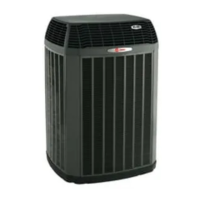
Recommendations for optimal unit placement to ensure performance.

2.4 Cold Climate Considerations

Precautions for units in areas with snow and freezing temperatures.

2.5 Coastal Considerations

Requirements for units installed near saltwater environments.

Section 3. Unit Preparation

3.1 Prepare The Unit For Installation

Steps to prepare the unit before installation, including damage check.

Section 4. Setting the Unit

4.1 Pad Installation

Guidelines for installing the unit on a support pad.

Section 5. Refrigerant Line Considerations

5.1 Refrigerant Line and Service Valve Connection Sizes

Table detailing line sizes and service valve connection sizes.

5.2 Factory Charge

Information on factory system charge for outdoor units.

5.3 Required Refrigerant Line Length

Guidance on determining required refrigerant line length and lift.

5.4 Refrigerant Line Insulation

Importance of insulating the vapor line and preventing contact.

5.5 Reuse Existing Refrigerant Lines

Precautions when using existing refrigerant lines for retrofit applications.

Section 6. Refrigerant Line Routing

6.1 Precautions

Guidelines to prevent noise from vibration transmission via refrigerant lines.

Section 7. Refrigerant Line Brazing

7.1 Braze The Refrigerant Lines

Step-by-step instructions for brazing refrigerant lines.

Section 8. Refrigerant Line Leak Check

8.1 Check For Leaks

Procedure to pressurize lines and check for leaks.

Section 9. Evacuation

9.1 Evacuate the Refrigerant Lines and Indoor Coil

Steps to evacuate refrigerant lines and indoor coil to a vacuum.

Section 10. Service Valves

10.1 Open the Gas Service Valve

Procedure for opening the gas service valve.

10.1 Open the Liquid Service Valve

Procedure for carefully opening the liquid line service valve.

Section 11. Electrical - Low Voltage

11.1 Low Voltage Maximum Wire Length

Table showing maximum allowed low voltage wire lengths by gauge.

11.2 Low Voltage Hook-up Diagrams

Wiring diagrams for low voltage connections to thermostats and air handlers.

Section 12. Electrical - High Voltage

12.1 High Voltage Power Supply

Information on matching high voltage supply to equipment nameplate.

12.2 High Voltage Disconnect Switch

Recommendation to install a separate disconnect switch for high voltage.

12.3 High Voltage Ground

Requirement to ground the outdoor unit per local codes.

Section 13. Start Up

13.1 System Start Up

Step-by-step guide for starting the installed system.

Section 14. System Charge Adjustment

14.1 Temperature Measurements

Procedures for measuring outdoor and indoor temperatures for charging.

14.2 Subcooling Charging in Cooling (Above 55° F Outdoor Temp.)

Method for charging system using subcooling above 55°F ambient.

14.3 Subcooling Charging Below 55° F Outdoor Temp.

Recommended method for charging below 55°F ambient using weighing.

Section 15. Checkout Procedures and Troubleshooting

15.1 Operational And Checkout Procedures

Final checks and procedures to ensure proper system operation.

15.2 Troubleshooting

Fault diagnosis and potential causes for system issues.

Related product manuals