E.
INSTALLING
REFRIGERANT
LINES
The
following
steps
are
to
be
considered
when
installing
the
refrigerant lines:
1. Determine
the
most
practical
way
to
run
the
lines.
2. Consider types
of
bends
to
be
made
and
space limita-
tions.
NOTE:
Large
diameter
tubing
sizes
will
be
difficult
to
bend
once
it
has
been
shaped.
3. Determine
the
best
starting
point for
routing
the
refrig-
erant
tubing
--INSIDE OR OUTSIDE
THE
STRUC-
TURE.
4.
Provide a
pull
through
hole of sufficient size
to
allow
both
liquid
and
gas lines
to
clear.
The
location of
this
hole
(if
practical) should
be
just
above
the
wall
plate
which
is
resting
on
the
foundation.
5. Be
sure
the
roll
of
tubing
is
of sufficient length.
6.
Uncoil
the
tubing-
do
not
kink
or dent.
7. Route
the
tubing
making
all required bends
and
prop-
erly secure
the
tubing
before malting final connections.
NOTE:
These
lines
must
be
isolated.
from
the
struc-
ture
and
the
holes
must
be
sealed
weather
tight
after
installation.
F.
FIELD
FABRICATED
INTERCONNECTING
LINES
The
following procedure should
be
used
for connecting tub-
ing
to
the
coil
or
the
outdoor
unit.
1. More information concerning
the
installation ofrefriger-
ant
lines is covered
in
the
Installers
Guide packaged
with
the
outdoor
unit.
Evacuation,
leak
testing
and
brazing procedures
are
included
in
those
instructions
before
starting
the
installation
of
refrigerant lines.
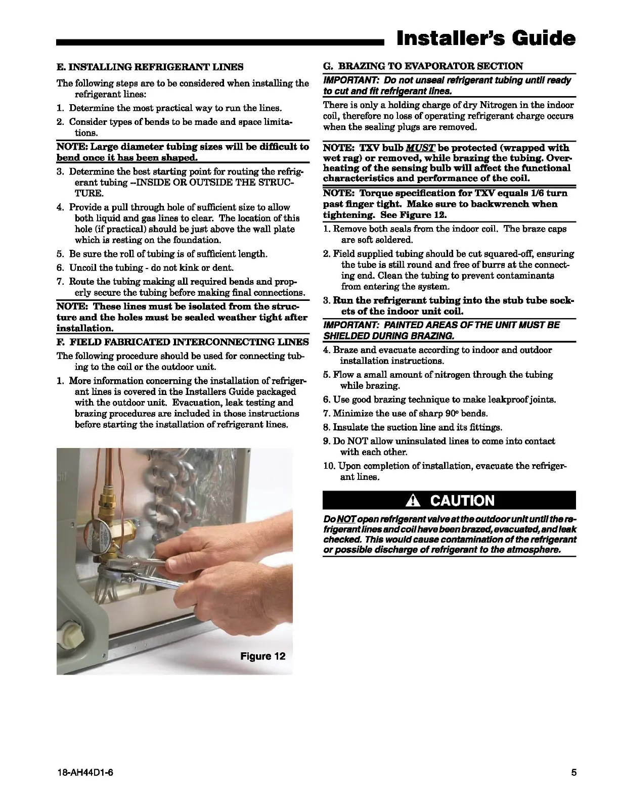
Figure 12
18-AH4401-6
Installer's
Guide
G.
BRAZING
TO
EVAPORATOR
SECTION
IMPORTANT:
Do
not
unseal refrigerant
tubing
until
ready
to
cut
and
fit
refrigerant
lines.
There
is
only a holding charge
of
dry
Nitrogen
in
the
indoor
coil, therefore no loss
of
operating refrigerant charge occurs
when
the
sealing plugs
are
removed.
NOTE:
TXV
bulb
MUST
be
protected
(wrapped
with
wet
rag)
or
removed,
while
brazing
the
tubing.
Over-
heating
of
the
sensing
bulb
will
affect
the
functional
characteristics
and
performance
of
the
coil.
NOTE:
Torque
specification
for
TXV
equals
1/6
turn
past
finger
tight.
Make
sure
to
backwrench
when
tightening.
See
Figure
12.
1.
Remove
both
seals from
the
indoor coil.
The
braze
caps
are
soft soldered.
2. Field supplied
tubing
should
be
cut
squared-off,
ensuring
the
tube
is
still
round
and
free
of
burrs
at
the
connect-
ing
end.
Clean
the
tubing
to
prevent
contaminants
from
entering
the
system.
3.
Run
the
refrigerant
tubing
into
the
stub
tube
sock-
ets
of
the
indoor
unit
coil.
IMPORTANT: PAINTED AREAS
OF
THE UNIT MUST
BE
SHIELDED DURING BRAZING.
4.
Braze
and
evacuate according
to
indoor
and
outdoor
installation instructions.
5.
li1ow
a
small
amount
of
nitrogen
through
the
tubing
while brazing.
6.
Use
good brazing technique
to
make
leakproofjoints.
7. Minimize
the
use
of
sharp
900
bends.
8.
Insulate
the
suction line
and
its
fittings.
9. Do
NOT allow
uninsulated
lines
to
come
into
contact
with
each
other.
10. Upon completion
of
installation, evacuate
the
refriger-
ant
lines.
A CAUTION
Do
Nm
open
refrigerant valve
at
the
outdoor
unit
until
the
re-
frigerant
lines
and
coil
hsvebeenbrszed, evacuated,
and
leak
checked. This
would
cause contamination
of
the
refrigerant
or
possible
discharge
of
refrigerant
to
the
atmosphere.
5