8
18-AH77D1-1A-EN
Refrigerant
Sensor
/
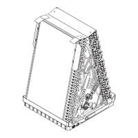
Figure 20
Figure 21
Refrigerant
Wrap tubes with wet
rags when brazing.
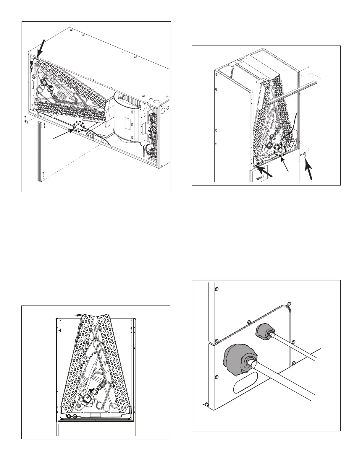
Figure 22
4.3.6 Coil Installation for Downflow Applications
1. Slide the replacement coil into the unit. See
Figure 20.
NOTE: Some modifications to the unit or return air duct
work may be required for downflow applications.
2. Reinstall coil retaining brackets. See Figure 21.
NOTE: Step is optional for downflow coil
replacements.
NOTE: For the “N” coils there is only one coil
retaining bracket on the unit. Additional retaining bracket
shipped with the replacement coil.
3. Reinstall lower horizontal brace(s). See Figure 21.
Figure 19
3. Reinstall coil and blower panels.
NOTE: Some replacement coil orders will ship with
multiple replacement line set panels. When neces-
sary, install the applicable panel and discard the
remaining panels.
4. Protect TXV bulb before brazing line set connections.
Important: TXV bulb MUST be protected (wrapped with
wet rag) or removed, while brazing the tubing Overheat-
ing of the sensing bulb will affect the functional charac-
teristics and performance of the comfort coil. See Figure
22.
4. If equipped, reinstall refrigerant sensor in same loca-
tion as before and reconnect. See Figure 21.
 Loading...