3
18-AH77D1-1A-EN
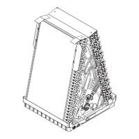
“A” coils
Square-cut coils
Figure 1
3.1 Common Preparation Steps
RISK OF FIRE!
In systems using flammable refrigerants, observe all
safety instructions and markings with the air handler.
Ensure all safety devices are in place and functional.
To be repaired only by trained professional. Do not
puncture refrigerant tubing. Dispose of properly in ac-
cordance with federal or local regulations.
1. Pump down or recover the refrigerant in the system.
2. Turn off high voltage power to the unit.
3. Remove the condensate drain lines from the indoor
coil. Be prepared to catch any water that might be in
the drain line and drain pan.
4. Disconnect the refrigerant lines to the indoor coil. Be
sure to protect the refrigerant lines so debris does
not enter the piping system.
5. Remove the air handler’s front panels. Retain all
screws to reinstall panels in a later step.
4. Upflow, Downflow, Horizontal Coil
Installation
4.1 Coil Removal
1. If your air handler is equipped with a refrigerant detec-
tion system sensor, remove and disconnect sensor.
Retain to reinstall in the same position later.
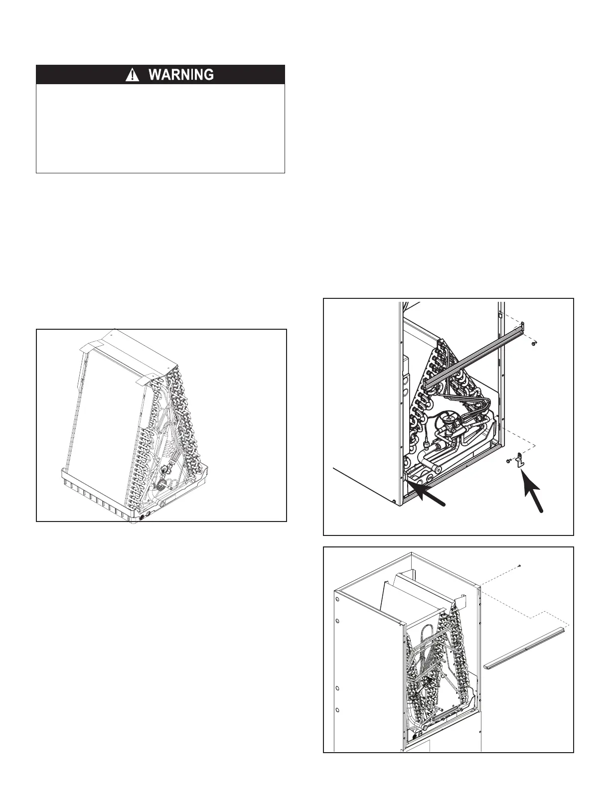
2. Remove the center brace and the two coil retaining
brackets. See Figures 2 and 4.
3. On the “N” coil only, remove the shipping bracket if
present. See Figure 4.
4. Remove coil assembly from the air handler by sliding
assembly outward. See Figure 5.
5. Remove and retain the horizontal drain pan to reinstall
later. See Figure 5.
4.1.1 Downflow Coil Removal
1. For downflow “N” coil replacement, remove lower
horizontal cross brace. See Figure 3.
2. On the “N” coil only, remove the shipping bracket if
present. See Figure 4.
3. Remove coil assembly from the air handler by sliding
assembly outward. See Figure 5.
NOTE: The “N” coil replacement is taller than the “N” coil,
see Figure 19. Some modification may be necessary to the
unit or the return ductwork in downflow applications.
4.1.2 TXV Removal (if equipped)
1. Remove TXV sensing bulb and equalizer fitting.
2. Remove TXV sensing bulb.
3. Loosen and remove TXV outlet fitting from distributor
assembly.
4. Protect the TXV assembly set so that debris does not
enter. Retain to reinstall later.
Figure 2
Figure 3
 Loading...