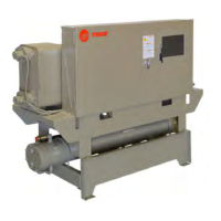
Dimensions and Weights
14 CG-SVX038A-EN
Table 5. CGWR/CCAR 40 to 65 ton — in (mm)
Dimension CGWR40 CGWR50 CGWR65 CCAR40 CCAR50 CCAR65
A
(a)
83.8 (2128) 83.8 (2128) 83.8 (2128) 87.6 (2225) 87.6 (2225) 87.6 (2225)
B 59.8 (1519) 59.8 (1519) 59.8 (1519) 45.8 (1163)* 45.8 (1163)* 45.8 (1163)*
C 13.1 (333) 13.6 (345) 13.6 (345) N/A N/A N/A
D 26.7 (678) 26.7 (678) 26.7 (678) 26.7 (678) 26.7 (678) 26.7 (678)
E 29.6 (752) 29.9 (759) 29.9 (759) 29.0 (737) 29.0 (737) 29.0 (737)
F 51.0 (1295) 51.0 (1295) 51.0 (1295) 51.0 (1295) 51.0 (1295) 51.0 (1295)
G 19.2 (488) 19.2 (488) 19.2 (488) 19.2 (488) 19.2 (488) 19.2 (488)
H 20 (508) 20 (508) 20 (508) N/A N/A N/A
I 36 (914) 36 (914) 36 (914) 36 (914) 36 (914) 36 (914)
J
(b)
36 (914) 36 (914) 36 (914) 36 (914) 36 (914) 36 (914)
K(b) 36 (914) 36 (914) 36 (914) 36 (914) 36 (914) 36 (914)
L 24 (610) 24 (610) 24 (610) 24 (610) 24 (610) 24 (610)
M 36 (914) 36 (914) 36 (914) 36 (914) 36 (914) 36 (914)
N 49.6 (1260) 49.6 (1260) 49.6 (1260) 35.6 (904)* 35.6 (904)* 35.6 (904)*
R 34.0 (864) 34.0 (864) 34.0 (864) 20.0 (508)* 20.0 (508)* 20.0 (508)*
S 13.4 (340) 13.4 (340) 13.4 (340) N/A N/A N/A
T 0.6 (15) 0.6 (15) 0.6 (15) 0.6 (15) 0.6 (15) 0.6 (15)
U 12.2 (310) 12.2 (310) 12.2 (310) 12.2 (310) 12.2 (310) 12.2 (310)
V 10.6 (269) 11.0 (279) 11.0 (279) N/A N/A N/A
W 15.5 (394) 16.8 (427) 16.8 (427) N/A N/A N/A
1 3.0 (76) VIC 3.0 (76) VIC 3.0 (76) VIC 3.0 (76) VIC 3.0 (76) VIC 3.0 (76) VIC
2 3.0 (76) VIC 3.0 (76) VIC 3.0 (76) VIC 3.0 (76) VIC 3.0 (76) VIC 3.0 (76) VIC
3 2.5 (64) FPT 3.0 (76) FPT 4.0 (102) FPT N/A N/A N/A
4 2.5 (64) FPT 3.0 (76) FPT 4.0 (102) FPT N/A N/A N/A
Reference
1 Evaporator Water Inlet 9
Condenser Opposite Inlet/Outlet End (CGWR only) —
minimum clearance (for maintenance)
2 Evaporator Water Outlet 10
Condenser Inlet/Outlet End (CGWR only) —
minimum clearance (for maintenance)
3 Condenser Water Inlet (CGWR only) 11 Condenser (CGWR only)
4 Condenser Water Outlet (CGWR only) 12 Evaporator
5 Power Disconnect (Optional) 13 Panel Power Section — door swing 31.3 in (795 mm)
6 Power Wire Entry 14 Panel Control Section — door swing 31.3 in (795 mm)
7 Control Wire Entry 15
Additional minimum clearance needed for units with water
regulating valve option
8 Control Panel 16
Location of CCAR refrigerant line connections, (2) 1-1/8 in
liquid line and (2) 1-3/8 in discharge lines
(a)For CGWR040, 050 and 065: If water regulating valve option is ordered, the overall length is 93.8 in, 95.0 in, and 96.2 in respectively.
(b)Exceptions:
1. A minimum clearance of 42 in (1067mm) is required to other electrically grounded parts.
2. A minimum clearance of 48 in (1220mm) is required between two units opposite each other (front-to-front or back-to-back), or to other electrically
live parts. See Section 110.26 of National Electrical code (NEC).

 Loading...