SS-SVX07B-E4 19
Installation
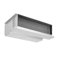
Connecting the ducts
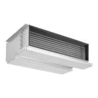
Units can be equipped with
rectangular discharge and/or intake
from the bottom or intake from the
back ducts.
WARNING!
The pressure loss in the network and
the accessories must not exceed the
unit's available static pressure given
in the selection data. The design and
installation shall be done by a
qualified technician and according to
local regulations.
Figure 8 - Discharge and intake duct
possibilities
A = Discharge
B = Intake from the bottom
C = Intake from the back
Table 12 - Duct connection dimensions
Unit size Length (mm) Height (mm)
512/518 748 198
524/530/536 948 248
048/060 1148 298
Filtering
Filtering the air is necessary to
ensure the unit's correct operation.
The unit is supplied with a filter.
Installing the wired
controller
Location
- Do not install thermostats near or
above a source of heat (i.e. direct
sunlight, hot lamps or radiator).
- Do not expose the controller to the
indoor unit discharge air stream.
- Do not place in a confined space.
Wiring
Electrical interconnection between
units must be in accordance with
national, state and local codes.
Units must be grounded. Refer to
the wiring diagrams that are shipped
with the unit.
 Loading...
