Do you have a question about the Trane Mitsubishi Electric TPEFYP006MA143A and is the answer not in the manual?
| Category | Air Conditioner |
|---|---|
| Model | TPEFYP006MA143A |
| Cooling Capacity | 6.0 kW |
| Refrigerant | R410A |
| Power Supply | 220-240V, 50Hz |
Read safety precautions, observe them, understand effects on power systems, and contact local authorities.
Explanation of warning and caution symbols indicating risks of injury, death, or damage.
Critical warnings on refrigerant use, proper installation, authorized accessories, no modifications, and handling sharp fins.
Safety advice on electrical parts, water exposure, control box covers, refrigerant types, and installation in confined spaces.
Guidelines for using phosphorus deoxidized copper piping, maintaining cleanliness, sealing ends, and using R410A-specific tools.
Procedures for handling R410A refrigerant, vacuum pumps, charging, and avoiding oil deterioration.
Table detailing cooling and heating capacities for different TPEFYP indoor unit models.
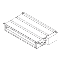
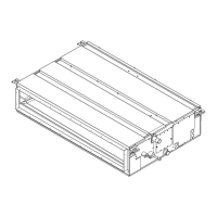
Diagrams showing indoor unit air inlet and outlet for rear and bottom inlet configurations.
Description of the remote controller interface, including buttons like ON/OFF, MENU, SELECT/HOLD, and function buttons.
Explanation of Full and Basic remote controller display modes and icons representing operational status.
Detailed specifications including power, capacity, dimensions, and fan data for TPEFYP006-015MA143A models.
Detailed specifications including power, capacity, dimensions, and fan data for TPEFYP018-030MA143A models.
Detailed specifications including power, capacity, dimensions, and fan data for TPEFYP036-054MA143A models.
Table detailing electrical components like thermistors, fuses, motors, and valves with their specifications.
Diagrams showing unit dimensions, mounting hole details, and refrigerant pipe connection sizes.
Diagrams and guidelines for creating adequate access space for unit maintenance and inspection.
Diagram illustrating the internal wiring of the control box and connections to various components and external units.
Diagram of the refrigerant system showing components like thermistors, expansion valve, and heat exchanger with pipe size details.
Details on initiating cool operation, setting temperature, and understanding thermo-regulating and anti-freezing functions.
Explanation of fan speed settings and the operation of the drain pump based on mode and float switch status.
Procedure for drying operation and its thermo-regulating function based on room temperature and set temperature.
Description of indoor fan operation control based on compressor conditions and remote controller settings in different modes.
Details on heat operation, hot adjust mode, fan control logic, and defrost operation.
Explanation of automatic Cool/Heat changeover logic and control functions when the unit is stopped.
Table and explanation for controlling the heater based on outdoor unit conditions and DIP switch settings.
Details on heater and fan control patterns, including DIP switch settings for ducted and non-ducted models.
Instructions for installing the optional External Heater Adapter, including parts list and connection details.
Wiring diagrams for connecting optional heaters and accessories to the indoor unit control board.
Methods for checking thermistors and linear expansion valve resistance against normal and abnormal values.
Explanation of the linear expansion valve's operation mechanism, pulse signals, and connection to the indoor control board.
Troubleshooting steps for locked or disconnected LEV, including checking driving circuits and coil resistance.
Procedures for checking the drain-up mechanism resistance and the drain float switch operation.
Troubleshooting guide for the indoor unit fan not running, covering connector checks, power supply, and motor signals.
Instructions for setting the address on rotary switches (SW11, SW12) for remote controller communication.
Diagram identifying key voltage test points on the indoor control board for troubleshooting purposes.
Overview of factory settings for DIP switches SW1 (Function) and SW3 (Unit Type, Heater Backup).
Settings for DIP switches SW2 (Capacity), SW4 (Model), and SW5 (Power Voltage) for unit configuration.
Explanation of DIP switch settings for external static pressure and rotary switch settings for address and connection number.
Procedure for removing the control box cover, including identifying screws and specifying tightening torque.
Steps for removing the intake air thermistor holder and thermistor from the control box area.
Instructions for removing the filter, bottom plate, and drainpan, including draining water first.
Procedure for removing the heat exchanger cover and the thermistors located on the copper tubes.
Steps for removing the fan casing, motor cable, fan motor, and Sirocco fan assembly.
Instructions for removing the heat exchanger cover and the heat exchanger unit, including screw torque.