10
RTRA model 107 108 108 HE-LF 109 109 HE-LF 110 110 HE-LF
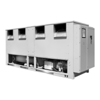
Figure 7A X (mm) N.A. N.A. 1800 1800 1800 1800 1800
Y (mm) N.A. N.A. 3450 3450 3450 3450 3450
Z (mm) N.A. N.A. 3350 3350 3350 3350 3350
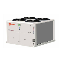
Figure 7B X (mm) N.A. N.A. 1800 1800 1800 1800 1800
Y (mm) N.A. N.A. 3250 3250 3250 3250 3250
Z (mm) N.A. N.A. 3550 3550 3550 3550 3550
Maxi weight (kg) N.A. N.A. 2940 3060 3330 3100 3380
Length (mm) N.A. N.A. 4566 4566 4566 4566 4566
Width (mm) N.A. N.A. 1300 1300 1300 1300 1300
Height (mm) N.A. N.A. 2000 2000 2000 2000 2000
N.A. : Not available.
Figure 7A - Right side
Figure 7B - Left side
Lifting and moving instructions
A specific lifting method is recommended as follows :
1. Four lifting points are built into the unit.
2. Slings and spreader bar to be provided by rigger and
attached to the four lifting points.
3. Minimum rated lifting capacity (vertical) of each sling
and speader bar shall not be less than tabulated unit
shipping weight.
4. Caution : this unit must be lifted with the utmost
care, avoid shock load by lifting slowly and evenly.
5. To be removed after unit installation.
 Loading...