EasyManua.ls Logo

Trane S8X1C100M5PSAB User Manual

Trane S8X1C100M5PSAB
64 pages
To Next Page IconTo Next Page
Page #1 background imageLoading...
Page #1 background image
SSAAFFEETTYY WWAARRNNIINNGG
Only qualified personnel should install and service the equipment. The installation, starting up, and servicing of heating, ventilating, and air-conditioning
equipment can be hazardous and requires specific knowledge and training. Improperly installed, adjusted or altered equipment by an unqualified person
could result in death or serious injury. When working on the equipment, observe all precautions in the literature and on the tags, stickers, and labels that
are attached to the equipment.
May 2020
1188--CCEE0044DD11--11DD--EENN
Upflow/Downflow/Horizontal
Gas-Fired, 1–Stage and 2–Stage Induced Draft Furnaces with
High Efficiency Motor
UUppffllooww,, DDoowwnnffllooww,, HHoorriizzoonnttaall RRiigghhtt//LLeefftt
Single Stage
S8X1A026M2PSAB
S8X1A040M3PSAB
S8X1B040M2PSAB
S8X1B060M3PSAB
S8X1B060M4PSAB
S8X1B080M4PSAB
S8X1C080M5PSAB
S8X1C100M5PSAB
S8X1D120M5PSAB
Two Stage
S8X2A040M3PSAB
S8X2B060M3PSAB
S8X2B060M4PSAB
S8X2B080M4PSAB
S8X2C080M5PSAB
S8X2C100M5PSAB
S8X2D120M5PSAB
S8X1
S8X2
NNoottee:: This installer’s Guide is used for multiple furnace families. Models
may have a “T” in the 12th digit designating they meet California less
than 40 ng/J (NOx) emissions requirements.
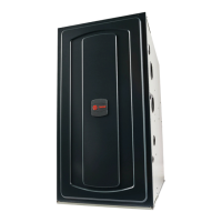
NNoottee:: Graphics in this document are for
representation only. Actual model may
differ in appearance.
18-CE04D1-1D-EN
Installer’s Guide
Question and Answer IconNeed help?

Do you have a question about the Trane S8X1C100M5PSAB and is the answer not in the manual?

Trane S8X1C100M5PSAB Specifications

General IconGeneral
BrandTrane
ModelS8X1C100M5PSAB
CategoryFurnace
LanguageEnglish

Summary

Safety Section Non-Condensing Furnaces

Fire, Explosion, and Electrical Hazards

Critical warnings about fire, explosion, and electrical shock risks during furnace installation and operation.

Carbon Monoxide and Venting Hazards

Warnings regarding carbon monoxide poisoning due to improper venting or damaged components.

Fire Hazard (Combustible Flooring)

Warning about fire risks, specifically concerning installation on combustible flooring.

Specific Safety Precautions

Electrical Safety & Component Handling

Guidelines on electrical safety, bypassing switches, and component interaction.

Operational Safety & CO Risk

Precautions for manual lighting, blower door security, and CO risks from improper installation.

Installation Site & Material Safety

Flammable Materials & Gas Connector Safety

Warnings about flammable materials, gas connectors, and filter placement.

High Voltage, Venting & Disconnect Safety

Safety measures for high voltage, venting, and electrical disconnect switches.

Voltage, Corrosion & Overheating Hazards

Cautions on improper voltage, corrosive atmospheres, and overheating risks.

Operational & Maintenance Safety

Handling, Service & Ignition Safety

Precautions for sharp edges, wrenches, ignition, and furnace service.

Environmental & System Safety

Warnings about freeze protection, water damage, and using the furnace as a construction heater.

Wiring & Hot Surface Precautions

Notes on wiring polarity and hot surface components like the igniter.

Equipment & Venting Safety

CO Hazard & Venting Procedures

Critical steps for safe operation of vented appliances to prevent CO poisoning.

Furnace Installation Guidelines

Safety Practices and Precautions

Essential safety rules to follow during installation, servicing, and operation of the furnace.

Locations and Clearances

Guidelines for selecting proper installation locations and maintaining required clearances.

Furnace General Installation

Gas Piping Installation

Upflow Orientation Gas Piping

Diagrams and notes for gas piping connections in upflow furnace orientations.

Downflow Orientation Gas Piping

Diagrams and notes for gas piping connections in downflow furnace orientations.

Horizontal Gas Piping Configurations

Horizontal Left Orientation Piping

Diagrams for gas piping in horizontal left orientation (top and bottom outlets).

Horizontal Right Orientation Piping

Diagrams for gas piping in horizontal right orientation (top and bottom outlets).

Combustion and Input Check

Gas Valve Adjustment

Manifold Pressure Adjustment Steps

Steps for adjusting manifold pressure for 1st and 2nd stage heating.

High Altitude Derate Procedures

General Venting

Air for Combustion and Ventilation

Confined Space Ventilation

Confined Space Air Supply Options

Guidelines for supplying combustion air in confined spaces, including outdoor and indoor air options.

Duct Connections

Return Duct Connections

Return Duct Connections (Continued)

Return Air Filters

Electrical Connections

Field Wiring Diagrams

Diagrams illustrating thermostat wiring for single-stage and two-stage heating systems.

General Start-up and Adjustment

Preliminary Inspections and Gas Checks

Steps for preliminary checks before startup, including gas leak detection.

Control and Safety Switch Checks

Procedures for checking limit switches and safety controls during initial startup.

Furnace Combustion Air Exhaust Options

Combustion Air Conversions

Integrated Furnace Control Menu (S8X1 Single Stage OD)

Integrated Furnace Control Menu (S8X1 Two Stage OD)

Integrated Furnace Control Menu (S8X2 Single Stage OD)

Integrated Furnace Control Menu (S8X2 Two Stage OD)

System Status Menu (S8X1 - S8X2)

Error Codes and Their Meanings

List and explanation of alarm error codes and their corresponding explanations.

Setting Airflow

Airflow vs. External Static Pressure Table

Table relating furnace airflow (CFM) to external static pressure for specific models.

Integrated Furnace Control Display Codes

Error Codes and Explanations

Comprehensive list of alarm error codes and their corresponding explanations.

Fault Code Recovery

Sequence of Operation S8X1/S8X2

1st Stage Gas Heating Operation Sequence

Detailed sequence of operations for 1st stage gas heating, including safety checks and ignition.

2nd Stage Gas Heating Operation (S8X2)

Detailed sequence for 2nd stage gas heating operation on S8X2 models.

Sequence of Operation (Continued)

Single Stage Cooling Operation Sequence

Sequence of operations for single stage cooling mode.

Two Stage Cooling Operation Sequence

Sequence of operations for two stage cooling mode.

Single Stage Heat Pump Operation Sequence

Sequence of operations for single stage heat pump mode.

Two Stage Heat Pump Operation Sequence

Sequence of operations for two stage heat pump mode.

Related product manuals