Do you have a question about the Transas NAVI-SAILOR 4100 ECDIS and is the answer not in the manual?
Specifies hardware and software prerequisites for NS 4000 MFD.
Details the installation process for NS 4000 ECDIS MFD workstations.
Covers the installation and specifications of the UPS6 unit.
Describes the DCU6 unit, its specifications, and connections.
Guides through the software installation for NS 4000 and NS 4100.
Explains how to configure the NS 4000 system settings.
Details how to set up and configure connected sensors.
Guides on installing charts and adjusting the Chart Assistant utility.
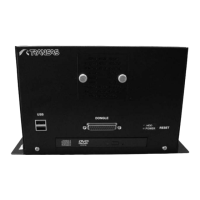
Details the general description, dimensions, and specifications of the RS6 computer.
Details the ES6 keyboard's functional description and technical data.
Explains the general description, purposes, and electrical characteristics of RIB6.
Details the input and output data formats used in the system.
Explains the functionality and standards for the Universal AIS Transponder interface.
Outlines methods for configuring the PIX-501-BUN-K9 firewall.
Provides network and FTP server settings for the communication PC.
Guides on adjusting NS 4000 operation with WAGO modules.
Details how to adjust NS 4000 operation with custom NMEA sentences.
Covers ship setup parameters and equipment layout configurations.
Covers configuration for COM ports, VIRT ports, and DCU ports.
Details ship limits and settings for track control mode.
Describes the RS6 computer and its extension board for serial ports.
Explains how to configure RS6 computer ports for NMEA0183 or RS232.
Guides on verifying the correct installation of RIB2 drivers.
Lists workstation elements and describes the RS4v2 computer.
Details the ES4 keyboard's functional description and technical data.
Explains the RIB's general description, purposes, and interface capabilities.
Illustrates the base configuration block diagram for the ECDIS MFD WS.
Provides a connection diagram for optional WS1 configuration.
| Radar Overlay | Yes |
|---|---|
| AIS Overlay | Yes |
| ARPA Target Tracking | Yes |
| Route Planning | Yes |
| Route Monitoring | Yes |
| Alarm Management | Yes |
| Power Supply | 24 VDC |
| Chart System | Transas TX-97 |
| Radar Interface | Yes |
| ECDIS Type | ECDIS |
| Operating System | Windows |
| Chart Format | S-57 |
| Positioning | GPS, GLONASS |
| Integration | Integrated |
| Compliance | IMO, IEC, IHO |
| Humidity | 95% |