EasyManua.ls Logo

Trek II SSP-3A-1 User Manual

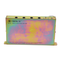
Trek II SSP-3A-1
6 pages
To Next Page IconTo Next Page
Page #1 background imageLoading...
Page #1 background image
The Trek II
®
SSP-3A solid state pre-amp is designed to replace the original tube pre-amps in standard Hammond
®
consoles.
In addition to basic pre-amp replacement, all units feature built in percussion circuitry, reverberation, auto power on
circuitry for 11 pin Leslie
®
speakers and built in tremolo control circuitry for Leslie speakers in the 122 family (models 21H,
22H, 22R, 31H above serial #5200, 122, 122A, 122R, 122RV, 122V, 142, 222, 222RV, and 242). Although not used in
normal installations, all units also have provisions for using a floor type (remote) swell control. The SSP-3A may also be
ordered with optional features including Auxiliary amplifiers, Effects loop, Remote tone and percussion controls. These
items, as well as hook up details for many other Leslie models are covered after the normal installation instructions.
Because of both electrical and mechanical variations in different vintage Hammond organs, the SSP-3A is available in a
number of different versions. The SSP-3A-1 version is specifically designed to replace the AO-28 pre-amp used in B-3, C-3,
D-152, and RT-3 model organs ONLY.
1. Remove original pre-amp, Leslie 8000 kit, if present, and reverb, if present.
2. Place the 3/8" lockwasher on the swell pot. Install the pot on the L bracket so that the locating tab engages the index
hole. Secure using 3/8" nut. Mount the bracket to the back of the pre-amp chassis, using 2) #6 x 1/4" screws.
SSP-3A-1 SOLID STATE PRE-AMP
GENERAL INFORMATION
WARNING! INSTALLATION OF THIS UNIT REQUIRES DIRECT CONNECTION TO THE AC POWER WIRING AND MUST
BE PERFORMED BY QUALIFIED PERSONNEL ONLY.
NOTE: PLEASE LEAVE THIS INSTRUCTION / SCHEMATIC SET IN ORGAN
COMPATIBILITY
INSTALLATION
WARNING! BEFORE PROCEEDING WITH INSTALLATION, DISCONNECT AC POWER FROM THE ORGAN AND
INSPECT THE CONSOLE POWER WIRING FOR BRITTLE OR ROTTING INSULATION.
TREK II PRODUCTS
570 JERSEY AVENUE NEW BRUNSWICK, NJ 08901 USA
TEL: 732-214-9200
FAX: 732-214-9257
www.TrekII.com
Rev. 06/06/05 © 2004 Trek II Products
1
2
3
4
SWELL POT
L BRACKET
WHITE
ORANGE
VIOLET
Question and Answer IconNeed help?

Do you have a question about the Trek II SSP-3A-1 and is the answer not in the manual?

Trek II SSP-3A-1 Specifications

General IconGeneral
Input Impedance10 kOhm
TypeSolid State Amplifier
Frequency Response20Hz - 20kHz +/- 1dB
Total Harmonic Distortion<0.1% at 1 kHz
Dimensions19" x 5.25" x 15"

Summary

General Information and Compatibility

General Information

Details the SSP-3A pre-amp's purpose, features like percussion, reverb, and tremolo control.

Compatibility

Specifies SSP-3A-1 version compatibility with B-3, C-3, D-152, and RT-3 organs.

Installation Procedure

Mounting the swell pot and bracket

Installing the swell pot onto the L bracket and mounting it to the pre-amp chassis.

Connecting the swell harness

Mating the 4-pin swell harness connector with P-4 and routing wires.

Wiring various connections

Connecting pilot lamp, Leslie tremolo, outlet box, vibrato, and percussion harness wires.

Securing chassis and components

Positioning the chassis, securing ground terminations, and mounting the unit.

Reverb and AC power connections

Installing the reverb unit and connecting the AC power socket.

Final adjustments and checks

Adjusting swell linkage, percussion controls, and attaching the cover.

Additional Features and Options

Remote Swell Control

Using a remote floor type swell pedal with the SSP-3A, including setup and wiring.

Auxiliary Amplifiers

Description of AUX-1 and AUX-2 amplifier channels and their input/output routing.

Additional Output Configurations

Outlet Wiring for Leslie Models (122XB, 315, etc.)

Wiring diagrams and notes for specific Leslie models, including 122XB, 315, 330, etc.

Outlet Wiring for Leslie Models (760, 770, etc.)

Wiring diagrams and notes for Leslie models 760, 770, 900, 910, 925.

Outlet Wiring for Leslie Models (44W, 45, etc.)

Wiring diagrams and notes for Leslie models 44W, 45, 46W, 47, 145, 147, etc.

Outlet Wiring for Leslie Models (51, 251, 351)

Wiring diagrams and notes for Leslie models 51, 251, 351, including warnings.

Wiring for Line Output

Diagram illustrating wiring for the unit's line output.

Related product manuals