HT/ST Installation Instructions - Sheet 1
HT/ST Space Humidity and Temperature Sensor Installation Instructions TG200921 Issue 1/B 30/08/06
1 - 2
LP2-PWR
TH
I2-N/TH
I1-N
JPR4
I1-P
EARTH
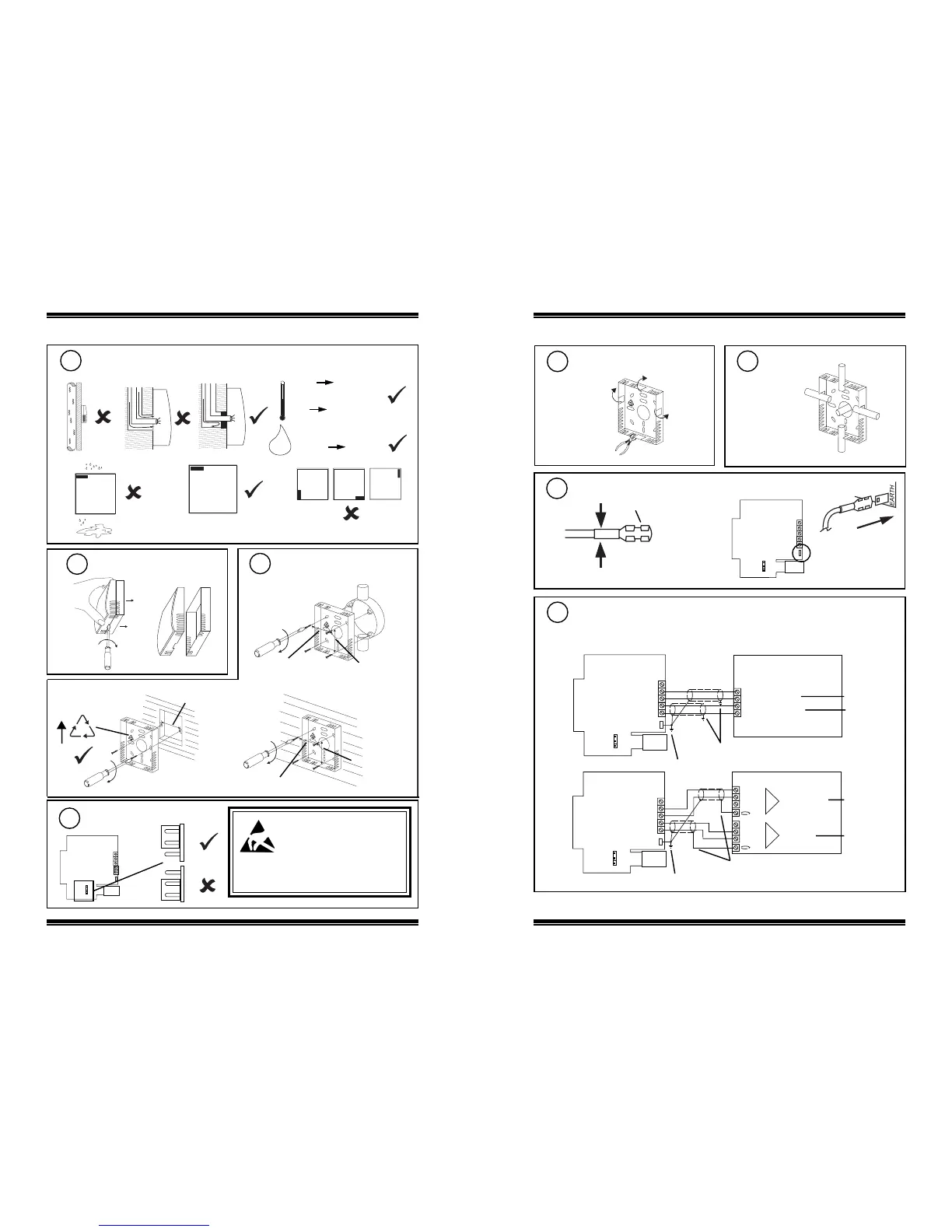
1.2 Installation (continued)
Requirements (continued)
2
i
j
H O
2
-20 °C
(-4 °F)
+60 °C
(140 °F)
0 %RH
100 %RH
non -condensing
h
0 °C
(32 °F)
+40 °C measurement
(104 °F)
lk
Mount backplate
4
wall
back box
(BESA)
35 mm (1.38”)
wall box
Remove backplate
3
a
b
60 mm (2.36”)
35 mm (1.38”)
35 mm (1.38”)
35 mm (1.38”)
FR
ABS
JPR4
Check link
5
JPR4
Caution: This unit contains static
sensitive devices. Suitable ant-
static precautions should be taken
throughout the operation to prevent
damage to the units.
BS EN100015/1 Basic Specifications: protection
of electrostatic sensitive devices.
HT/ST Space Humidity and Temperature Sensor Installation Instructions TG200921 Issue 1/B 30/08/06
1 - 3
Installation Instructions - Sheet 1 HT/ST
1.2 Installation (continued)
Remove cutout(s)
6
Route cables
7
as required
Wire to Controller
9
Sensor
IQ1 & IQ2
} temperature
} humidity
linked for
thermistor (T)
linked for
current (I)
2 analog input
channels
Sensor
IQ3
temperature
humidity
linked for
thermistor (T)
linked for
current (I)
earth (ground) screens and board earth at sensor end
earth (ground) screens and board earth at sensor end
Note that for CE compliance: Ensure that the sensor end cable
screens and board earth ground wire are connected to the
nearest (<1.5 m) earth ground. Ensure that the controller end
cable screens are connected to the controller earth ground.
Connect board earth
8
LP2-PWR
TH
I2-N/TH
I1-N
JPR4
I1-P
EARTH
terminate screens at IQ end
terminate screens at IQ end
a
b
crimp cable
‘fast on’ socket supplied
 Loading...