CaterSense the Intelligent answer
CS-INSTV2-0.01 Page 7 01-15
Model: CaterSense V2
Remaining Terminals are the larger terminals (4 mm² cable) and are for the power
connections for the fans, gas valve and power supply to the unit.
The terminals are of the rising clamp type with protection.
All cabling should be kept to the top of the unit within the designated area. No cables should
be placed or laid across the PCBs as this may cause damage.
1.05 System set-up
The CaterSense V2 unit has a number of intelligent control solutions. Each of which is set via
a DIL (DIP) switch mounted on the main PCB circuit board. The CaterSense also has a
unique “Self-set” system commissioning tool which makes for easy system commissioning.
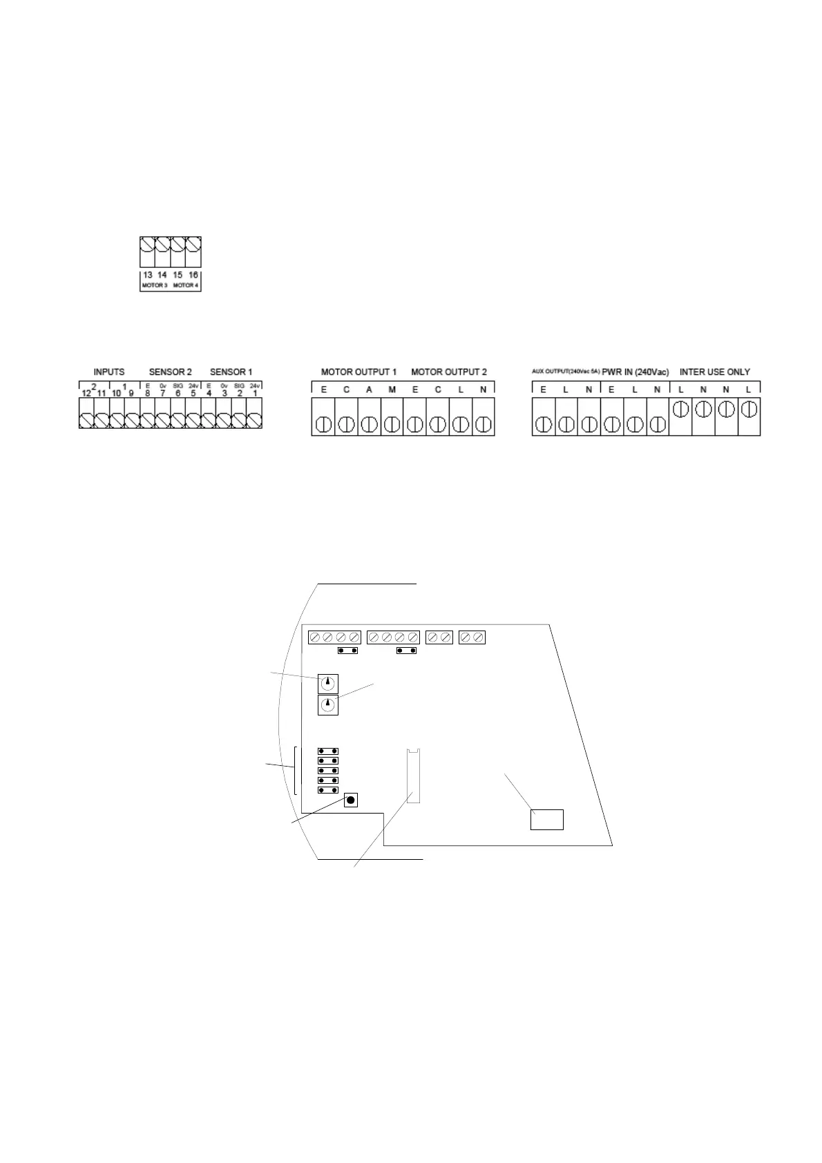
These devices are located on the main PCB as detailed in Diagram 3.
2.0 Set-up and Commissioning
The set-up and commissioning of your CaterSense system is in two parts, Initial and
System.
2.01 Initial Set-up
Once all of the wiring has been completed and tested and the system is ready to be set-up
and commissioned, the following sequence MUST be followed to ensure the CaterSense and
system operate correctly.
OFF
ON
1 2 3 4
R113
R114
SENSOR 1
SENSOR 2
KNOCK-OFF
FIRE ALARM
SET-UP
CONTROLLER
MODE DIL SWITCH
SYSTEM
SET-POINT 2
SYSTEM
SET-POINT 1
INPUT SELECTION
JUMPERS
ENGINEERS SYSTEM
SELF-SET BUTTON
MAIN PCB
SINGLE FAN
RIBBON CABLE
SOCKET
J27
J26
J25
J23
J13
J5J3
Diagram 3: PCB locations
 Loading...