CaterSense the Intelligent answer
CS-INSTV2-0.01 Page 6 01-15
Model: CaterSense V2
1.03 Cable entry
1.03A For standard control unit:
The CaterSense V2 enclosure has an area of 190 x 25 mm which can be drilled for conduit
entry on the top edge of the enclosure.
1.03B For inbuilt speed control unit:
The CaterSense V2 & ATSC has two main areas for cable entry: the top area (223 x 40mm)
and the back of the enclosure (130 x 30mm located at the top).
For ease of installation, most of the connections you will need are made in the enclosure for
the ATSC. The inter-connections between the ATSC and the CaterSense controller are
achieved via two pre-made cable looms.
1.04 Electrical connections
1.04A For standard control unit:
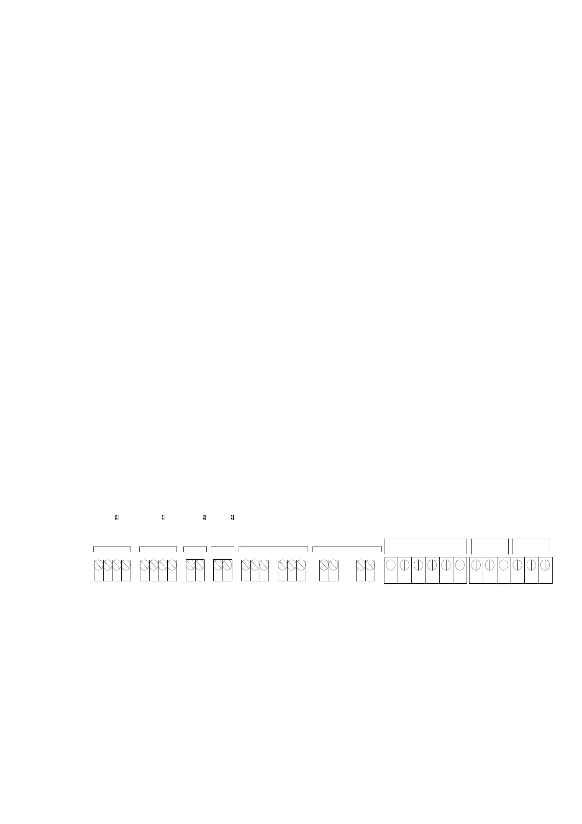
The CaterSense system has two sets of terminals all mounted along the top edge of the main
PCB circuit board.
Terminals 1 to 22 are the smaller terminals (1.5 mm² cable) and are used for the
sensors, inter-locking devices, remote speed and on/off control,
screened cable must be used (we recommend Beldon 8723 but
that should be the choice of the installer and dependant on the
individual installation).
Terminals 23 to 34 are the larger terminals (4 mm² cable) and are for the power
connections for the fans, gas valve and power supply to the unit.
The terminals are of the rising clamp type protection.
All cabling should be kept to the top of the unit within the designated area. No cables should
be placed or laid across the PCBs as this may cause damage.
SENSOR 1 SENSOR 2
FIRE
ALARM
REMOTE
KOPB
CONTROL OUTPUTS
VOLT-FREE
OP1 OP2
CONTROL OUTPUTS
0-10V SPEED SIGNAL
OP3 OP4
START / STOP
POWER SIGNALS
FAN 1 FAN 2
GAS VALVE
OUTPUT
POWER
SUPPLY
E NL
E N
L
E E L NL N
1 2 3 4 5 6 7 8 9 10 11 12 13 14 15 16 17 18 19 20 21 22 23 24 25 26 27 28 29 30 31 32 33 34
REMOVE JUMPER LINK TO ACTIVATE DEVICE
J27 J26 J23 J25
4 Amp Max
24v 0vS+ S- 24v 0vS+ S- S+ 0v Scr S+ 0v Scr
1.04B For inbuilt speed control unit:
The ATSC-02-xx system has two sets of terminals all mounted along the top edge of the main
PCB circuit board.
Terminals 1 to 16, are the smaller terminals (1.5 mm² cable) and are used for the
sensors and inter-locking devices including motor thermal contacts.
Screened cable must be used (we recommend Beldon 8723 but
that should be the choice of the installer and dependant on the
individual installation).
 Loading...