14
MAINTENANCE
REPAIR
It is recommended that periodic inspection of all parts of the pump be made to prevent malfunctions
caused by worn or broken parts. Disassembly for repair is the same procedure as for cleaning. This
seal design is used in applications where a vacuum tight, cool operating seal is required. This seal
consists of two carbon seals inside a stuffing box, which is attached to the backplate. Its sealing
action is the same as the external balanced seal.
1. WATER MUST BE PIPED THROUGH THE STUFFING BOX TO KEEP THE SEAL COOL AND
VACUUM TIGHT. The amount of water used will vary depending on the operating temperature of
the pump. In vacuum applications 10 drops per minute discharge is recommended, while
approximately 3 gallons per hour is required to maintain seal temperature at 100°F (38°C) when
the product temperature is 175°F (79°C).
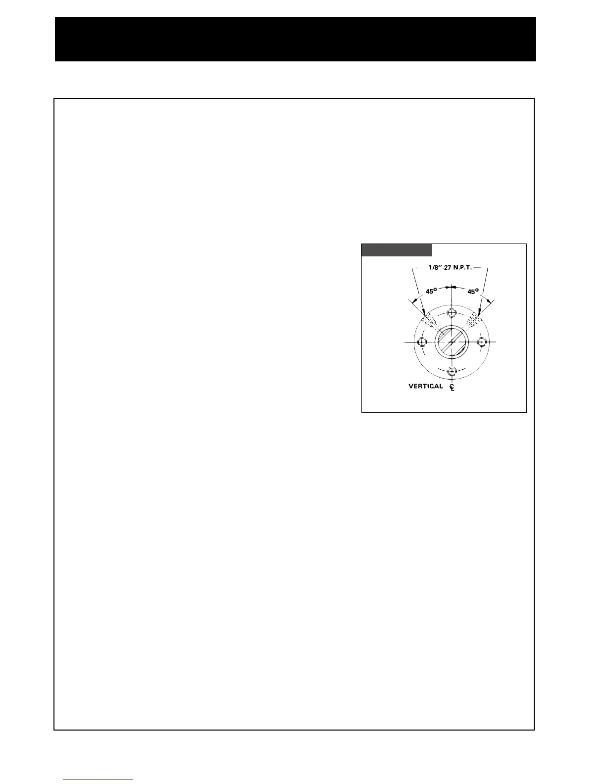
2. Two
1
/8" NPT water connections are provided on the stuffing
box. They are spaced at 90° from each other, and should
be located when assembling the pump so that they are at
45° to vertical. Flush water must enter one of these
connections and exit through the other connection. Refer to
figure 4.
3. Carefully inspect the o-ring seals and the carbon seals for
signs of abrasions, cuts or other wear that would cause
leakage. When the extension of the carbon seal face
extends less than
1
/32" from the body, it is advisable that the
carbon seal be replaced. Inspect backplate seal surface and
follower seal surface for nicks or scratches. Replace if
necessary.
4. Remove the rubber shaft deflector by prying it gently from
the rear, while sliding it forward. Examine the deflector for tearing, loose fit, or other defects that
would allow fluid leakage into the motor along the armature shaft.
5. Remove the bolts securing the adapter to the motor frame and remove the adapter. Loosen the 4
set screws securing the stub shaft by prying from the back with a flat bar. The stub shaft is a tight
fit but can be removed by evenly applying pressure around the periphery of the shaft with the pry
bar.
6. Examine the stub shaft sealing surfaces for nicks or scratches which can cause excessive o-ring
seal wear or leaking.
7. Attach a hoist to the motor if necessary, and remove the bolts securing the motor to the adjusting
leg brackets. Remove the set screws securing the adjustable legs and remove the legs.
Note:
The metal displaced by the setscrews on the adjustable legs makes it necessary to tap the
legs out with soft hammer. Rough spots should be filed down prior to reassembly.
8. Inspect casing clamp for damage or wear, and replace as required. Inspect the adjusting legs,
adjusting leg brackets, adapter and casing and replace if necessary.
9. Motor maintenance, repair and wiring are not covered in this manual. For specific information
contact the motor manufacturer.
REASSEMBLY
1. Assemble the adjusting legs to the adjusting leg brackets, and assemble the brackets to the motor.
Level the motor by individually adjusting the legs and locking them in place with set screws.
2. Install the adapter to the motor, with the drain cavity at the bottom. Insert the four bolts securing
the adapter to the motor. Tighten the bolts securely.
Figure Four
E Seal
 Loading...