15
MAINTENANCE
3. Assemble the stub shaft to the motor armature shaft. Do not tighten set screws.
4. Install the backplate into the counter-bore in the adapter.
For floating retainer models
Rotate the shaft until the floating pin hole is in a horizontal position. Insert the floating retainer, center
it in the shaft, and slide the impeller on the shaft. Hold the impeller tight against the shoulder on the
shaft and rotate the shaft one-fourth turn until the floating retainer drops and engages the impeller.
For threaded shaft models
Slide the impeller on the shaft and replace washer and castellated nut and cotter pin. Use a
combination of washers if needed to ensure that the castellated nut is tight on the impeller before
inserting and securing cotter pin.
For both models
1. Assemble the clamp to the adapter, and install the casing.
2. Push the stub shaft onto the motor shaft until the impeller
strikes the inside front face of the backplate. Locate the stub
shaft on the motor shaft allowing
1
/16" (1.5mm) maximum
clearance between the rear face of the impeller and the inside
face of the backplate. Tighten the four set screws on the stub
shaft. At a location behind the backplate, scribe a mark on the
shaft (refer to Figure 5). This will be required to set the drive
collar location as described in this section.
3. Remove casing, impeller and backplate.
4. Slide the rubber deflector on the shaft until it seats the groove
in the shaft.
Note:
If the deflector cannot be forced on with the fingers, a blunt
instrument can be used to provide additional force at the
I.D. of the deflector.
5. Slide the follower, one carbon seal, one seal o-ring, one seal
cup, and drive collar onto the shaft.
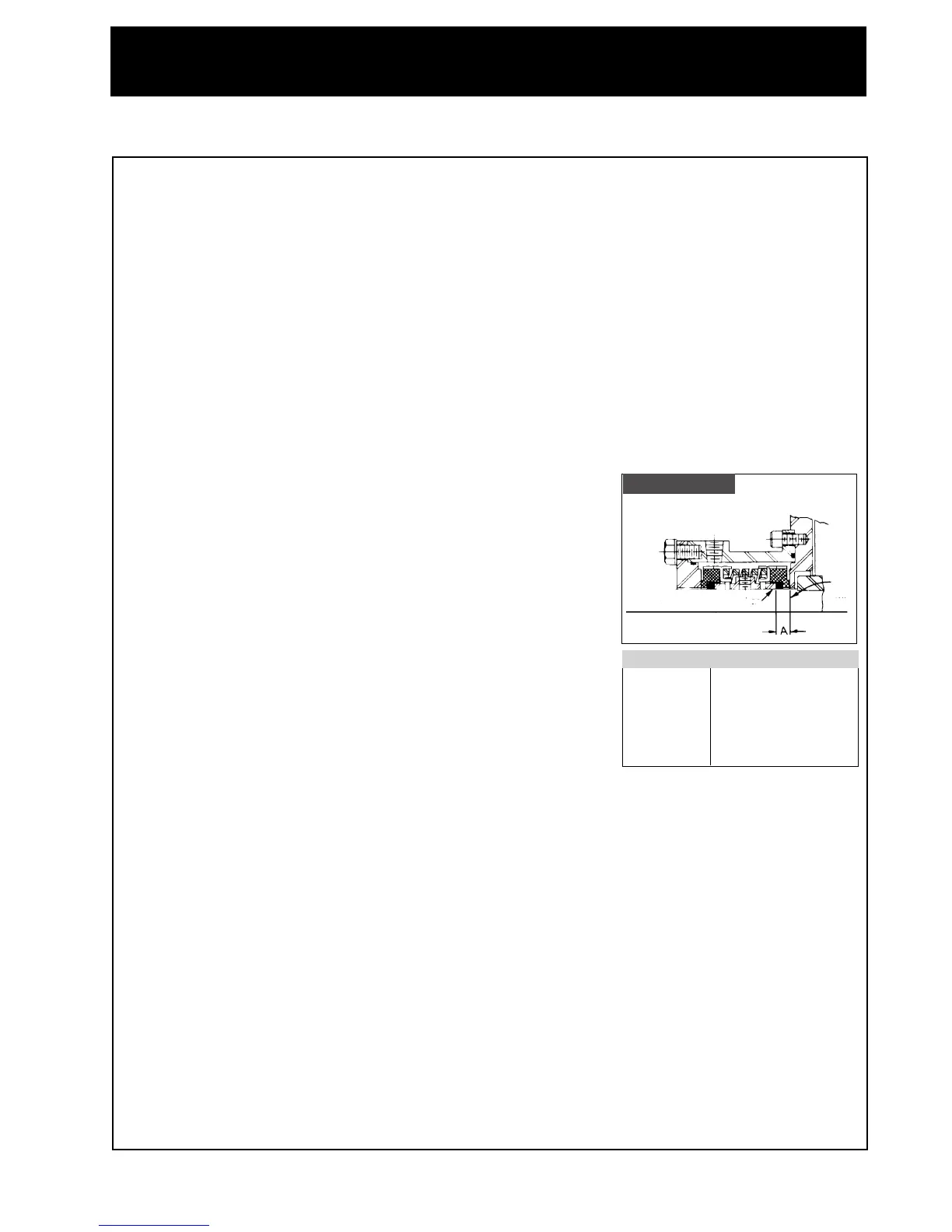
6. Locate drive collar in relation to scribe mark as shown in Figure
5 and secure to the shaft with the set screws. Drive collar location is critical.
7. Install the seal spring, seal cup, seal o-ring and carbon onto the shaft. Be sure the spring is
seated in each cup and the drive ear on each seal cup is not in alignment with the drive pins on
the drive collar.
8. Slide the stuffing box and backplate assembly over the shaft and seal parts.
9. Secure the follower to the stuffing box using four screws.
10. Assemble the backplate, the impeller, and the casing to the pump and tighten clamp, tapping with
soft hammer. (Make sure the orientation of the water connection on the stuffing box is correct
Figure 5).
11. Assemble seal guard and tighten nut.
12. Connect the water inlet and outlet piping to the stuffing box.
13. Assemble the suction and discharge piping to the pump.
14. Check for strain on the casing. Adjust as required.
Drive Collar Setting
SCRIBE
MARK
front end of drive collar
Figure Five
E Seal
Model "A" Dimension
114
11
/32" (2.3mm)
216
11
/32" (2.3mm)
218
11
/32" (2.3mm)
328
11
/32" (2.3mm)
4410
11
/32" (2.3mm)
 Loading...