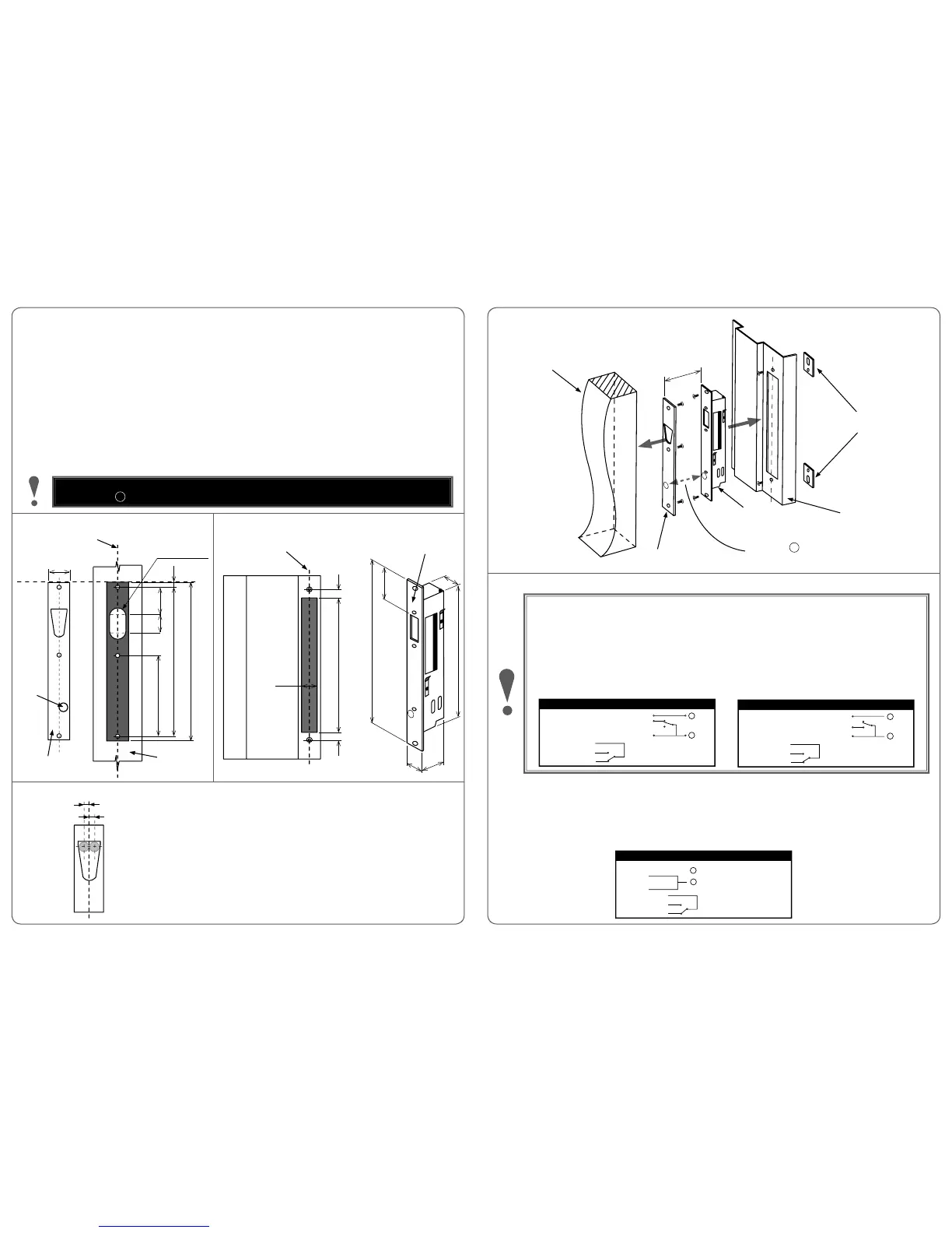
Mark LINE 1 corresponding to mid-plane of door (see 1. Fig. 1).
On door jamb, mark LINE 2 which will be in line with LINE 1 (see 2. Fig. 2).
Mark cutout of V-Lock symmetrically about LINE 2. Cutout size must be 256mm x 30mm. Thickness of strike plate and lock 3.
faceplate are 3mm each. Prepare door jamb appropriately as shown in Fig. 2.
Ensure all wiring is correctly connected and not rubbing on sharp edges or interfering with any lock mechanism. 4.
Install lock unit into door jamb as shown in 5. Fig. 3.
On the door, mark LINE 3 corresponding to the top edge of lock faceplate (see 6. Fig. 1). Mark and recess cutout of strike plate
on door symetrically about LINE 1, and using LINE 3 as reference.
Install strike plate on door, and ensure that door gap between strike plate and lock faceplate is between 3mm and 8mm 7.
only (see Fig. 3).
Power up lock, then let door open and close normally with door closer. When strike plate magnet comes within locking range, 8.
the V-Lock unit will lock as long as lock bolt closes within target locking range (see Detail A).
Fig. 1 - Door Preparation
For locking bolt on V-Lock unit to attempt locking, strike plate magnet MUST be correctly aligned and in •
front of the M mark on the lock faceplate. Lock will not operate without strike plate.
Fig. 2 - Door Jamb Preparation
Detail A - Target Locking Range
If door closes outside target locking range (+/- 3.5mm), V-Lock will execute 5 locking •
attempts.
If lock bolt cannot enter the strike hole after 5 attempts, lock will cease • operation to
prevent motor burn-out.
When this happens, adjust door closer or re-position strike plate. To restart • locking
sequence, send another door open/close signal to the V-Lock.
Fig. 3 - V-Lock Installation
ELECTRICAL SPECIFICATIONS
The V-Lock is designed to be controlled with a minimum of 3 wires. Positive voltage should be connected to the
RED wire providing permanent power, a second negative wire connected to BLACK and a third positive voltage
wire connected to BLUE providing a lock/unlock signal. When connected with 3 wires the motor will provide
power assisted unlocking allowing the bolt to retract with up to 15kg of side load. Voltage-free changeover
switch contacts are provided for bolt position monitoring. When locked, the monitor switch (COM - PURPLE) is
connected to (NC - ORANGE).
The V-Lock is multi-voltage and operates with either 12 to 24vDC power. It has in-built Reverse Polarity Protection
for installer safety. For a lock in locked position, wiring diagrams for both Power-To-Open (Fail Secure) and Power-
To-Lock (Fail Safe) are found below:
Bolt Position
Monitor
Power To Lock (PTL) Wiring Connections
- Access Control (PTL)
ORANGE
BLACK
BLUE
RED
PURPLE
WHITE
- 0 volts d.c.
- Positive Continuous Supply
- (COM)
- (NO)
- (NC)
-
+
DC Power
NC
NO
Bolt Position
Monitor
Power To Open (PTO) Wiring Connections
ORANGE
BLACK
BLUE
RED
PURPLE
WHITE
- 0 volts d.c.
- Access Control (PTO)
- Positive Continuous Supply
- (COM)
- (NO)
- (NC)
NC
NO
-
+
DC Power
In Power-To-Lock (Fail Safe) confi guration, it is possible to operate the V-Lock using 2 control wires only. With 2 wire control
the lock relies on the Fail Safe spring mechanism to unlock, which reduces the lock’s capability to open under side load to only
3kg. Hence, 2 wire control is NOT RECOMMENDED and should be avoided wherever possible.
For retrofi t applications where only 2 control wires may exist, connect the BLUE and RED wires on the lock together and join
them to the positive supply voltage. Connect the negative supply voltage to the BLACK wire on the lock (see below).
Bolt Position
Monitor
Power To Lock 2 Wire Control - NOT RECOMMENDED
ORANGE
BLACK
BLUE
RED
PURPLE
WHITE
- 0 volts d.c.
- (COM)
- (NO)
- (NC)
-
+
DC Power
256
Strike Plate
3mm Thickness
7
48
242
24132
D22 x 20 Deep
27
Door
LINE 3
LINE 1
(Half thickness of door)
M
Lock
Faceplate
256 1515
30
30
256
50
24
42
210
Door Jamb
LINE 2
Magnet
Maximum door gap
3mm - 8mm
Strike Plate
V-Lock Unit
Door Jamb
Door
M
Mounting Tabs (supplied)
Required for Flush Mounting only
Magnet and M must line
up for V-Lock to operate
3.5mm
3.5mm
INSTALLATION
 Loading...